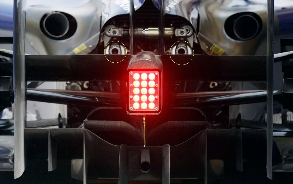
richard_leeds wrote:It would be interesting to hear more about this approach.
I'll have an attempt.
Basic spring elements on the rear suspension of most F1 vehicles comprise "corner" torsion springs (Kc), a "3rd" coil spring (Kt), an arb (Ka). In addition, non-linear elements such as bump rubbers &/or bellevilles and packers can be added to the "corner" dampers and the "3rd" element (slider, damper or inerter). Just to make life interesting, suspension geometry can be non-linear (usually "rising rate") & the degree of non-linearity can be different for corner elements, the 3rd element & the arb.
To keep the discussion simple, ignore non-linear elements, assume geometry is linear, and consider the overall axle stiffness to have a "heave/pitch" component (Kh) & a "roll" component (Kr). Then
Kh = G1*Kc + G2*Kt (i.e. is a linear combination of the corner & 3rd spring stiffness).
Kr = G3*Kc + G4*Ka (a linear combination of the corner & arb spring stiffness).
It follows that, when all elements are present, Kh cannot be less than the larger of G1*Kc and G2*Kt, whilst Kr cannot be less than the larger of G3*Kc and G4*Ka. The common element is Kc. Minimum values for both Kh & Kr are prescribed once a value of Kc has been selected. Further, any change to the value of Kc will change both Kh & Kr.
Normally it is convenient to be able to change Kh & Kr independently when "tuning" a suspension set-up. This can be achieved by restricting changes to the 3rd and arb elements, which is fine provided than neither is required to be < 0. The most flexible arrangement would be to remove the corner springs entirely, & this will work provided that sufficient ranges of values are available for both the 3rd and arb elements, and the "installation stiffness" of both elements is adequate. From the latter viewpoint, the most efficient structural arrangement is often to share loads between all elements.

