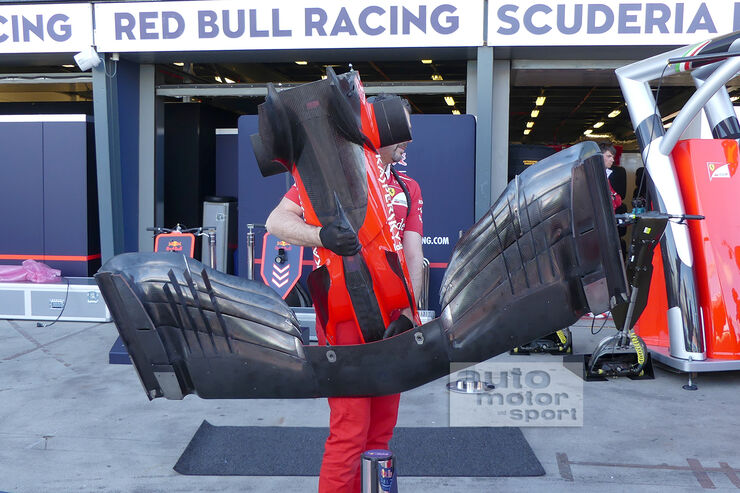
Scuderia Ferrari SF70H

A place to discuss the characteristics of the cars in Formula One, both current as well as historical. Laptimes, driver worshipping and team chatter do not belong here.
User avatar
Vanja #66
1569
Joined: 19 Mar 2012, 16:38

Re: Scuderia Ferrari SF70H

Post

Why do you think this solution costs a lot of drag? Perhaps a bit more drag compared to RB13, but compared to any other car... I seriously doubt it.
And they call it a stall. A STALL!

#DwarvesAreNaturalSprinters
#BlessYouLaddie

Agerasia
Agerasia
0
Joined: 14 Jan 2009, 14:08

Re: Scuderia Ferrari SF70H

Post

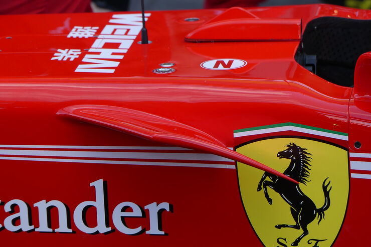
The more I look at this, especially the 3rd picture, the more I become convinced the top part is so much more than a flow conditioner. I see a classic swept back aerofoil design, which would make sense when both sides are taken into the equation. That would be a significant amount of downforce.
"badically pressuring rosnerg " Ringo 05/10/2014

Fer.Fan
Fer.Fan
0
Joined: 02 Mar 2015, 21:31

Re: Scuderia Ferrari SF70H

Post

Vanja #66 wrote:Hey guys, long time no see! I've had a lot of thought about those beautiful SF70H sidepods and I think I have them figured out... Please note the think word. :)

First off, they are obviously very aggressive and seemingly contradict a lot of what we think is going on with conventional designs. With such an opening on top, perpendicular to the flow at first look, it really makes you wonder... Well, naturally, it can't be perpendicular and it has to fit in the bigger picture of the whole design. This picture started it all (all of the original pictures can be found previously in this thread):

http://oi67.tinypic.com/ff7bxk.jpg

What we see inside is a set of flaps in a position seen when airplanes land - maximum lift and therefore maximum bending angle of the flow once it passes trailing edge. There are two flaps in fact, you can just see the leading edge of the first one, so it's not a continual surface starting from the leading edge of the outer flap. This is expected, in front of the radiator you need to build up the pressure using an intake and this creates adverse pressure gradient in this area - so you need flaps and slots to energize the flow and keep it attached. There are more elements in front of the radiator there, but they aren't interesting at this point. The top element of sidepod opening (and yes, I think we should be looking at this as the actual opening, not as flow conditioners) seems to be almost parallel to ground level or at a slight angle. This is very unusual as this would normally create flow separation since the airflow coming to the sidepods is already bent up by the front wing (putting the sidepod at a high angle of attack so to speak). Last year, SF16-H had very thick top leading edge of the sidepods as a first step to counter this potential separation.

http://www.f1fanatic.co.uk/wp-content/u ... -front.jpg

This year the roles are reversed, it's the lower edge that is a lot thicker, perhaps event thicker than the top one on SF16-H.

https://pbs.twimg.com/media/C5a3PecWUAAr_5d.jpg

This suggests that the airflow should be coming to the sidepod parallel to the ground or perhaps even at a negative angle. FIA restriction on nose camera mounting is not a problem for Ferrari with this concept and you can see how different their position is now.

Look at the picture above again and you can see that the first set of winglets on the chassis is almost parallel to the top of the tub (and so almost parallel to ground level), while the one closer to the sidepods is at a relatively high AoA and is turning the airflow downwards. At the back, in the sidepod, you can see those two flaps in a similar position.

https://pbs.twimg.com/media/C5a5MSiWgAAGvvv.jpg

On this picture you can see even better how the angle of winglets changes from front to back. At the front there are two of them with a slot energizing the airflow and keeping it attached. Tip vortices probably aren't too strong.

https://pbs.twimg.com/media/C5a3AYcXEAAUg8f.jpg

Now looking at this picture you can see how it all falls into the big picture, with these winglets turning the airflow near the chassis, i.e. in the boundary layer. From experience I know how tricky it is keeping the flow attached in the bottom part of the sidepod intake next to the chassis, as you have a boundary layer, airflow bent up by front wing and bent a bit sideways by cockpit expansion in the chassis. Last two years I was a leading aerodynamicist in Formula Student team from Belgrade, last year we designed and made our first radiator intake. This area was very unstable in CFD and on track we had some separation. However the intake was a success as the avg water temperature was some 5-6 deg C lower than the year before, event with a 20% smaller radiator surface area.

http://i66.tinypic.com/sazipv.jpg

http://i67.tinypic.com/2yun2wh.jpg

It's a whole different world compared to F1 of course, but the principles are the same. We also left an opening to separate the boundary layer next to our bodywork, similar to the small opening with a mesh SF70H has in the sidepod. Finally, flow conditioners/brackets on the outer edge of the sidepod opening are there to keep it in check. Seeing them this twisted suggests just how much the flow changes near the actual opening.

http://i63.tinypic.com/2m6wt42.png

The one thing I'm not sure about is whether this sidepod upper flap is separated and slotted, or is it a single piece extending outboard. These two pictures seem to tell a different story:

https://imgr3.auto-motor-und-sport.de/S ... 010129.jpg

http://i20.photobucket.com/albums/b227/ ... rp2erx.jpg

In the end, to put it simply, this is what I think is going on:

http://oi67.tinypic.com/280i4d1.jpg

And here I drew up what could be happening overall. A long shot, yes, but we are here to discuss.

http://oi64.tinypic.com/6h6uf8.jpg

With this concept Ferrari could have provided quite a larger amount of air to the back of the car coming from under the sidepod opening. Also, top sidepod opening is in a position where the flow starts bending downwards on the sidepod top surface so the lower pressure that is created there has a smaller effect (in contact with a smaller surface). So Ferrari could have made two big steps in this area - maximizing the amount of air going to the top of the diffuser and minimizing the lift created on top of the sidepods.
=D> =D> =D> =D> =D> =D> =D> =D> =D>
Brilliant post Vanja 66. I read it several times and it is brilliant.
You are right specially om this one;
Also, top sidepod opening is in a position where the flow starts bending downwards on the sidepod top surface so the lower pressure that is created there has a smaller effect (in contact with a smaller surface).

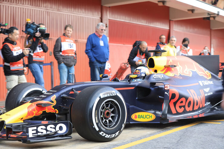
This is what Red Bull is doing with their sidepod shape.
Image

ripper
ripper
39
Joined: 26 Aug 2015, 22:19

Re: Scuderia Ferrari SF70H

Post

What is the advantage of using two pilon RW support ? Ferrari should be the only team with this solution, everyone else is using monopylon through exahaust pipe. Are they trying to "use" hot gas flows in some way?

roon
roon
412
Joined: 17 Dec 2016, 19:04

Re: Scuderia Ferrari SF70H

Post

ripper wrote:What is the advantage of using two pilon RW support ? Ferrari should be the only team with this solution, everyone else is using monopylon through exahaust pipe. Are they trying to "use" hot gas flows in some way?
What I noticed about them was that they permit lower bodywork, as there is no structure over the exhaust pipe. It's only pipe, then a small gap, then the engine cover.

That, and these swan necks literally look like swans' necks.

Image

Two black swans... Is that a good omen, or a bad omen?

User avatar
PlatinumZealot
559
Joined: 12 Jun 2008, 03:45

Re: Scuderia Ferrari SF70H

Post

They have been beheaded so they shouldn't be a threat anymore.
🖐️✌️☝️👀👌✍️🐎🏆🙏

Racing Green in 2028

tpe
tpe
-4
Joined: 03 Feb 2006, 00:24
Location: Greece

Re: Scuderia Ferrari SF70H

Post

Can someone explain here why they say that the Mercedes and RB diffusers are more detailed/advanced of the Ferrari's solution? I would really like to understand what makes a diffuser a to produce more downforce than diffuser b, design wise.

User avatar
F1Krof
94
Joined: 22 Feb 2016, 21:17

Re: Scuderia Ferrari SF70H

Post

roon wrote:
ripper wrote:What is the advantage of using two pilon RW support ? Ferrari should be the only team with this solution, everyone else is using monopylon through exahaust pipe. Are they trying to "use" hot gas flows in some way?
What I noticed about them was that they permit lower bodywork, as there is no structure over the exhaust pipe. It's only pipe, then a small gap, then the engine cover.

That, and these swan necks literally look like swans' necks.

https://i.imgur.com/O3GZ4M1h.jpg

Two black swans... Is that a good omen, or a bad omen?
The omen is clear:

Thou shalt be a two swan race to the crown,
And the horse will carry the hero to the stand above the two Plated Stars and the Flaming Bulls.
But who will the hero be?
The Fiery Juvenile to Quinary Crown?
Or the Icy Elder to the Double Showdown?

Unduly close to foretell for now!
Wroom wroom

User avatar
Mr.G
34
Joined: 10 Feb 2010, 22:52
Location: Slovakia

Re: Scuderia Ferrari SF70H

Post

360 VR video of SF70H - https://www.youtube.com/watch?v=4kRNW9MP3bo so if you have VR set, enjoy...
Art without engineering is dreaming. Engineering without art is calculating. Steven K. Roberts

User avatar
Mr.G
34
Joined: 10 Feb 2010, 22:52
Location: Slovakia

Re: Scuderia Ferrari SF70H

Post

Art without engineering is dreaming. Engineering without art is calculating. Steven K. Roberts

User avatar
Godius
186
Joined: 02 Mar 2013, 12:49
Location: NL

Re: Scuderia Ferrari SF70H

Post

s-duct channels

AMuS:

Image

Image

Image

Image

User avatar
Thunder
Moderator
Joined: 06 Feb 2013, 09:50
Location: Germany

Re: Scuderia Ferrari SF70H

Post

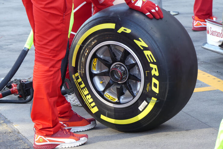
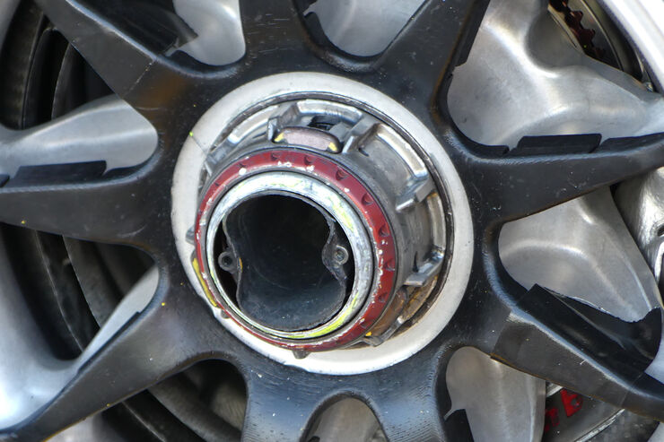
New Rims or just repainted?
Image

Also not sure that was there before.
Image
turbof1 wrote: YOU SHALL NOT......STALLLLL!!!
#aerogollum

User avatar
Mr.G
34
Joined: 10 Feb 2010, 22:52
Location: Slovakia

Re: Scuderia Ferrari SF70H

Post

Thunders wrote:
23 Mar 2017, 09:55
New Rims or just repainted?
https://imgr2.auto-motor-und-sport.de/F ... 060566.jpg

Also not sure that was there before.
https://imgr4.auto-motor-und-sport.de/F ... 060567.jpg
It's some kind of protection plastic (3D printed), it will go off... Here closer look

Image

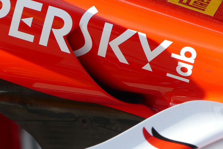
Looks like new S-duct intake shape to me.
Image
Image
Art without engineering is dreaming. Engineering without art is calculating. Steven K. Roberts

User avatar
SR71
5
Joined: 27 Jan 2016, 21:23

Re: Scuderia Ferrari SF70H

Post


Cross over S duct is interesting.

Are they (1) trying to lengthen and smooth out the air passage or (2) take air from the high pressure side in yaw and feed it to the opposite side of the car?

.poz
.poz
50
Joined: 08 Mar 2012, 16:44

Re: Scuderia Ferrari SF70H

Post

Image