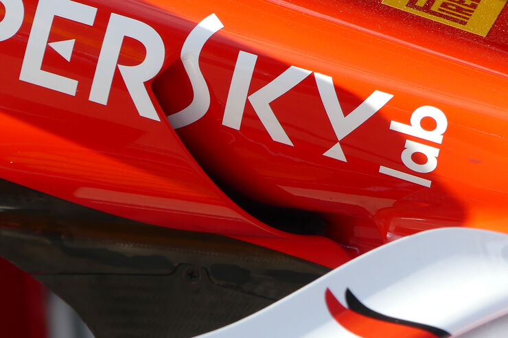
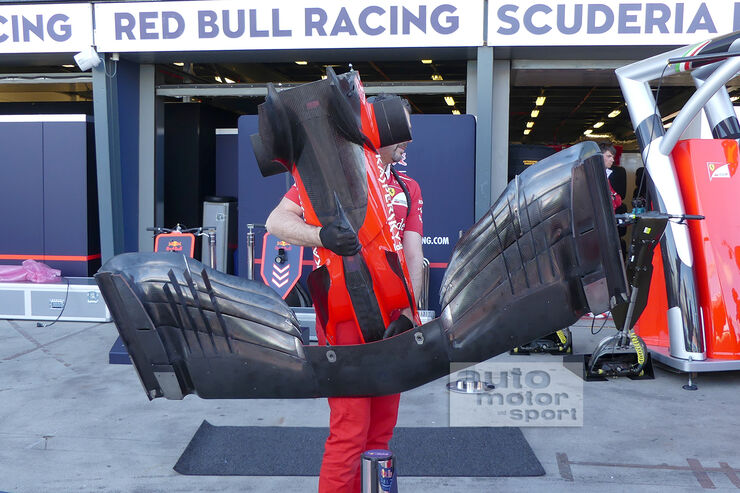
Vanja #66 wrote:Hey guys, long time no see! I've had a lot of thought about those beautiful SF70H sidepods and I think I have them figured out... Please note the
think word.

First off, they are obviously very aggressive and seemingly contradict a lot of what we think is going on with conventional designs. With such an opening on top, perpendicular to the flow at first look, it really makes you wonder... Well, naturally, it can't be perpendicular and it has to fit in the bigger picture of the whole design. This picture started it all (all of the original pictures can be found previously in this thread):
http://oi67.tinypic.com/ff7bxk.jpg
What we see inside is a set of flaps in a position seen when airplanes land - maximum lift and therefore maximum bending angle of the flow once it passes trailing edge. There are two flaps in fact, you can just see the leading edge of the first one, so it's not a continual surface starting from the leading edge of the outer flap. This is expected, in front of the radiator you need to build up the pressure using an intake and this creates adverse pressure gradient in this area - so you need flaps and slots to energize the flow and keep it attached. There are more elements in front of the radiator there, but they aren't interesting at this point. The top element of sidepod opening (and yes, I think we should be looking at this as the actual opening, not as flow conditioners) seems to be almost parallel to ground level or at a slight angle. This is very unusual as this would normally create flow separation since the airflow coming to the sidepods is already bent up by the front wing (putting the sidepod at a high angle of attack so to speak). Last year, SF16-H had very thick top leading edge of the sidepods as a first step to counter this potential separation.
http://www.f1fanatic.co.uk/wp-content/u ... -front.jpg
This year the roles are reversed, it's the lower edge that is a lot thicker, perhaps event thicker than the top one on SF16-H.
https://pbs.twimg.com/media/C5a3PecWUAAr_5d.jpg
This suggests that the airflow should be coming to the sidepod parallel to the ground or perhaps even at a negative angle. FIA restriction on nose camera mounting is not a problem for Ferrari with this concept and you can see how different their position is now.
Look at the picture above again and you can see that the first set of winglets on the chassis is almost parallel to the top of the tub (and so almost parallel to ground level), while the one closer to the sidepods is at a relatively high AoA and is turning the airflow downwards. At the back, in the sidepod, you can see those two flaps in a similar position.
https://pbs.twimg.com/media/C5a5MSiWgAAGvvv.jpg
On this picture you can see even better how the angle of winglets changes from front to back. At the front there are two of them with a slot energizing the airflow and keeping it attached. Tip vortices probably aren't too strong.
https://pbs.twimg.com/media/C5a3AYcXEAAUg8f.jpg
Now looking at this picture you can see how it all falls into the big picture, with these winglets turning the airflow near the chassis, i.e. in the boundary layer. From experience I know how tricky it is keeping the flow attached in the bottom part of the sidepod intake next to the chassis, as you have a boundary layer, airflow bent up by front wing and bent a bit sideways by cockpit expansion in the chassis. Last two years I was a leading aerodynamicist in Formula Student team from Belgrade, last year we designed and made our first radiator intake. This area was very unstable in CFD and on track we had some separation. However the intake was a success as the avg water temperature was some 5-6 deg C lower than the year before, event with a 20% smaller radiator surface area.
http://i66.tinypic.com/sazipv.jpg
http://i67.tinypic.com/2yun2wh.jpg
It's a whole different world compared to F1 of course, but the principles are the same. We also left an opening to separate the boundary layer next to our bodywork, similar to the small opening with a mesh SF70H has in the sidepod. Finally, flow conditioners/brackets on the outer edge of the sidepod opening are there to keep it in check. Seeing them this twisted suggests just how much the flow changes near the actual opening.
http://i63.tinypic.com/2m6wt42.png
The one thing I'm not sure about is whether this sidepod upper flap is separated and slotted, or is it a single piece extending outboard. These two pictures seem to tell a different story:
https://imgr3.auto-motor-und-sport.de/S ... 010129.jpg
http://i20.photobucket.com/albums/b227/ ... rp2erx.jpg
In the end, to put it simply, this is what I think is going on:
http://oi67.tinypic.com/280i4d1.jpg
And here I drew up what could be happening overall. A long shot, yes, but we are here to discuss.
http://oi64.tinypic.com/6h6uf8.jpg
With this concept Ferrari could have provided quite a larger amount of air to the back of the car coming from under the sidepod opening. Also, top sidepod opening is in a position where the flow starts bending downwards on the sidepod top surface so the lower pressure that is created there has a smaller effect (in contact with a smaller surface). So Ferrari could have made two big steps in this area - maximizing the amount of air going to the top of the diffuser and minimizing the lift created on top of the sidepods.
