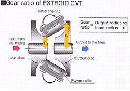
The input disk turns at the gearbox rpm speed. The output disk is coupled to the storage disk using a gear (let's say, with a 3:1 gear ratio) to increment the rpms of the storage disk.
The CVT works like this: the input and output disks are coupled by a viscous liquid. The closer the input and output disk are, the faster the output disk rotates. You have a mechanism to close the gap between input and output disks: the viscous liquid works like a clutch or an hydraulic automatic transmission.
Those rotational speeds you mention are nothing new. There are UPSs (Uninterrupted power supply) for computers based on flywheels that, from memory (we talked about them in the first KERS threads, a couple of years ago) reach 200,000 rpm since the 90's.
They are larger than the dimensions you mention. The storage disks are made of carbon fiber to withstand rotational forces at larger radii. The storage disk is within a cilinder that is able to contain the shards produced if the storage disk disintegrates.
Those units are used (like batteries) in computer rooms without any problem that I know. It could be argued that regular batteries are as dangerous as flywheels: what if a hydrogen-producing battery explodes and throws acid to the driver?
Actually, those flywheels are pretty clever: they don't use regular but magnetic bearings and the sleeve of the bearings works as a molecular air pump to keep the vacuum inside the storage disk. The magnetic bearings have circuitry that senses if the flywheel deviates from its axis and correct it in real time, and, if it senses that the flywheel is out of balance and it's going to break, stop the unit.
Pentadyne flywheel and magnetic levitating circuitry; they call units using steel disks "first generation flywheels"


