Rotary valve technology

All that has to do with the power train, gearbox, clutch, fuels and lubricants, etc. Generally the mechanical side of Formula One.
HowlerMonkey
HowlerMonkey
1
Joined: 08 Sep 2013, 05:06
Location: West Palm Beach, Florida

Re: Rotary valve technology

Post

LOL........I knew the last page of this thread would still be discussing sealing.

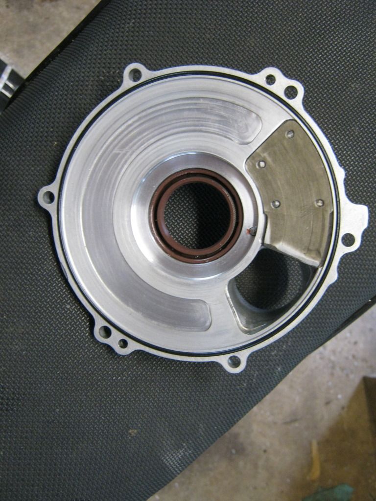
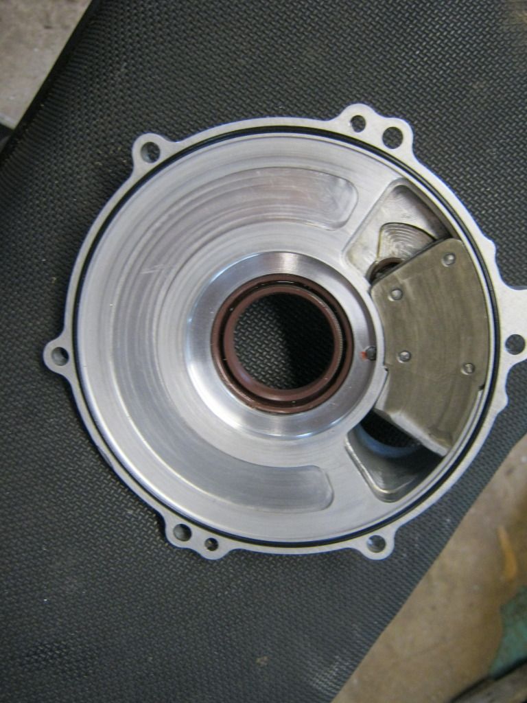
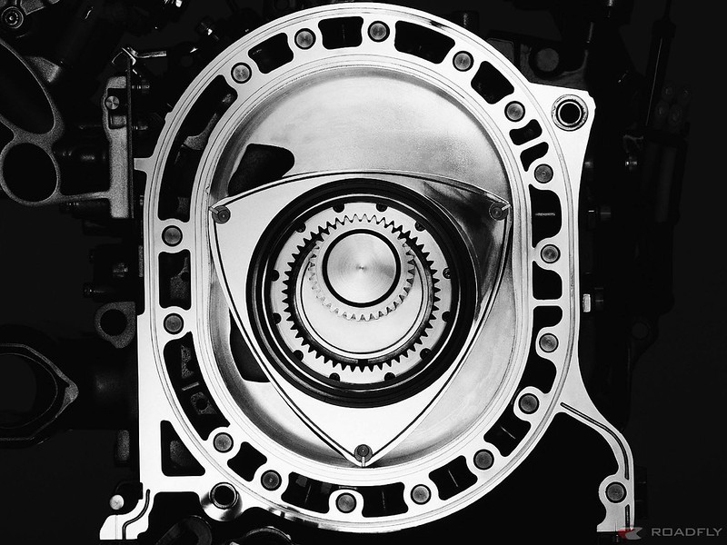
Look!!!.......a sealed rotary valve!!!

No, not the apex seals..............the side seals.
Image

bigpat
bigpat
19
Joined: 29 Mar 2012, 01:50

Re: Rotary valve technology

Post

Except that in a rotary (Wankel) engine, the valve is stationary, and the rotor moves....

I drove a high power 100cc go kart for a number of years, that was rotary valve induction. Compared to reed valve it has less bottom end torque, but when the power came on at 10-11000 rpm is was awesome!!! Top end power was its strength, no doubt. It also had a lot more induction noise that a reed valve engine, as there are no reeds to muffle it.

HowlerMonkey
HowlerMonkey
1
Joined: 08 Sep 2013, 05:06
Location: West Palm Beach, Florida

Re: Rotary valve technology

Post

The rotor is the valve.

The ports are stationary.

zenji
zenji
0
Joined: 23 Sep 2013, 01:22
Location: Australia

Re: Rotary valve technology

Post

I bet if you made that head for pit bikes / lifan style motors you could knock 00's of them out cheap?
The 4 valve head conversion for them is $350 aud, i bet you could bang out those rotary heads for less.
Slip one in the old CT110 postie bike and do some endurance runs.
Wonder if it would make it around the country?

manolis
manolis
107
Joined: 18 Mar 2014, 10:00

Re: Rotary valve technology

Post

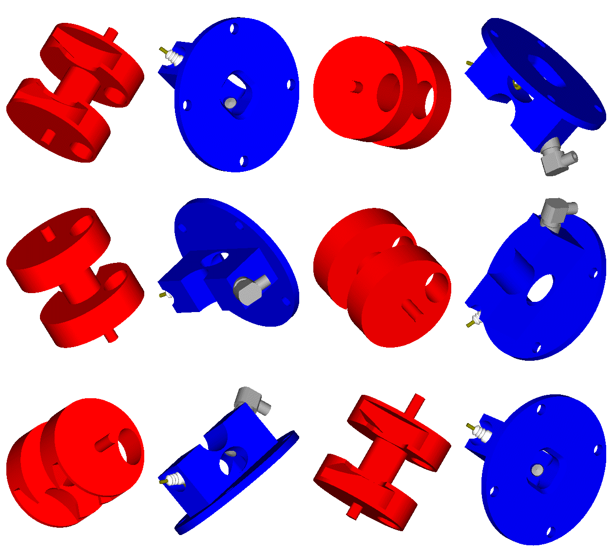
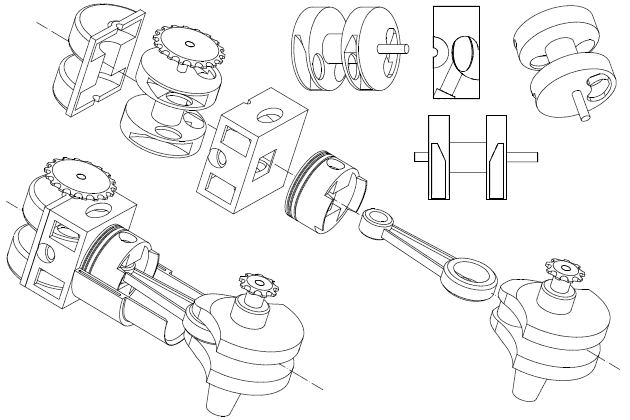
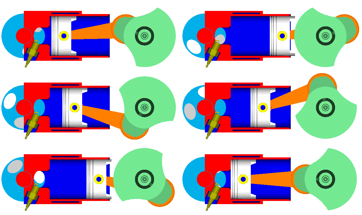
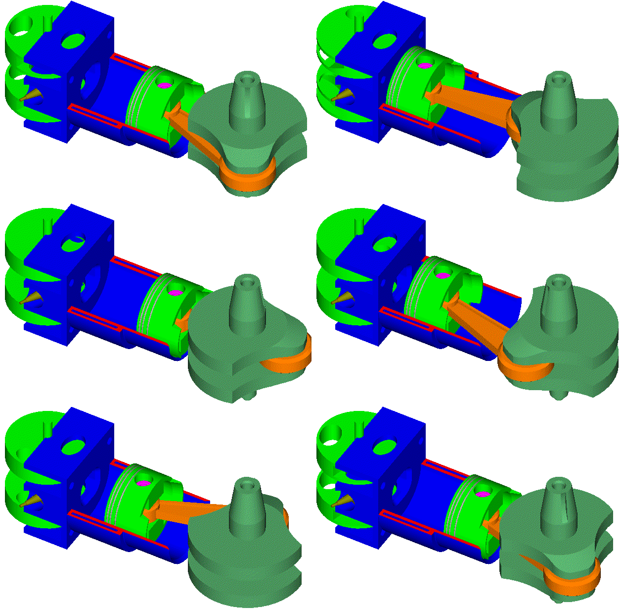
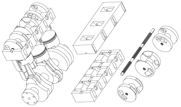
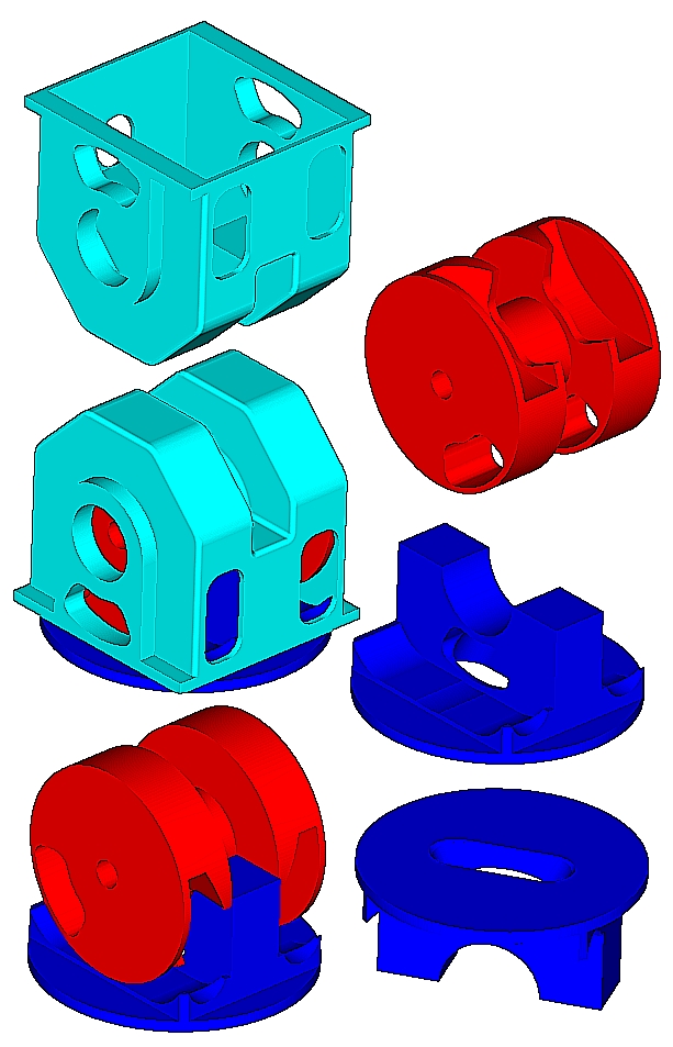
At http://www.pattakon.com/pattakonPatRoVa.htm it is presented a Disk Rotary Valve.
It comprises a pair of oppositely acting fronts firmly secured to each other.
The fronts seal a pair of oppositely arranged ports (chamber ports) of the combustion chamber.

Image
Image
Image

The overall "pressure" force acting on the rotary valve is from small to zero, leaving its bearings unloaded.

The combustion chamber is rid of hot spots (like, for instance, the hot exhaust poppet valves of the conventional engines, or like the hot chamber ports of the state-of-the-art exhaust rotary valves). Every point of the combustion chamber is equally related with the intake and with the exhaust. On this reasoning the compression ratio can further increase.

Image

Multicylinders: a splined shaft drives all the rotary valves of a line (or bank) of cylinders.

Image

Without having a pathway to the exhaust, any gas leakage from the combustion chamber during the compression / combustion is recycled: it returns into the cylinder at the next suction cycle.

Image

Any thoughts?

Thanks
Manolis Pattakos

OdinYggd
OdinYggd
3
Joined: 29 Jan 2014, 02:30

Re: Rotary valve technology

Post

While that approach might work if you were able to keep the seals tight to the surfaces, the long distance from chamber to valve leaves a lot of dead space at compression that will conspire to limit its maximum efficiency. This is actually one of the areas where the poppet valve is consistently superior to most rotary and sleeve valves- the valves can be fitted very tightly to the chamber to keep the clearance volume down to a minimum.

I've been working on the rotary valve seal problem off and on for some time now, and having access to a machine shop and supply of scrap metal to make mechanical test structures out of have built a few test valves.

My earliest build was nothing more than a tight fit metal to metal. This of course leaks like no tomorrow- with a calculated compression pressure of 180 PSI it only measures about 30 PSI. Surprisingly the engine actually does fire in this configuration, but it does not produce enough power to sustain.

Simply adding o-rings to it doesn't help either. They get nibbled by the port edges and destroyed.

I'm working on a new idea right now, but I need to figure out how to seal the sides of it. If I can pull that off, I'll have the rotary valve sealing problem almost completely solved, and in a rather novel way.

uniflow
uniflow
36
Joined: 26 Jul 2014, 10:41

Re: Rotary valve technology

Post

Image

Image

Image

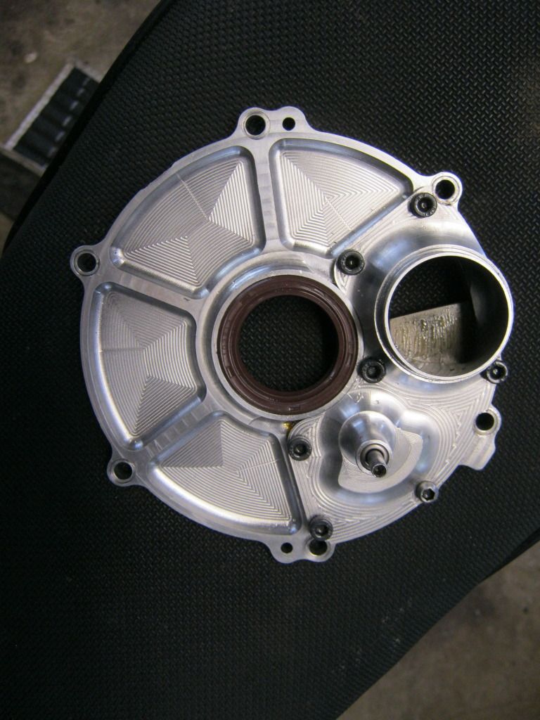
Vairable rotary valve inlet, twostroke. Changes the shut time of the valve for good low speed and high speed crank case filling. Will beat a reed motor! ECU control.

uniflow
uniflow
36
Joined: 26 Jul 2014, 10:41

Re: Rotary valve technology

Post

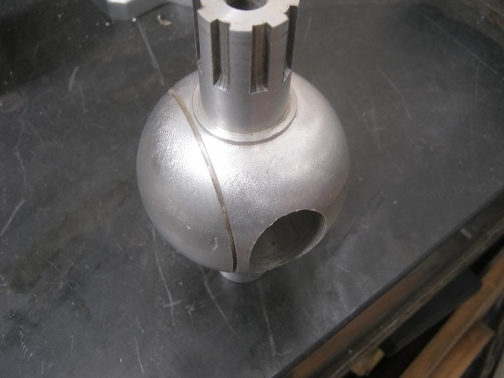
Here is a ball valve. Note the piston ring groove, works as if it's in a bore. This valve is hollow for cooling.

Image

User avatar
PlatinumZealot
559
Joined: 12 Jun 2008, 03:45

Re: Rotary valve technology

Post

hardingfv32 wrote:
n smikle wrote:... If your sealing gap (if there is one at all) is small enough and if there is another row of sealing especially the gasses will have to slow down to extremely slow speeds to even pass through, it is almost like the flow has to be laminar! That is asking alot from a big flaming ball of fire in the combustion chamber...
This is incorrect. The slightest leak at a poppet valve seat can be observed on the dyno as a loss of performance.

Brian
Talking about rotary valves here. Obviously a seated type of valve will only have one boundary for sealing so if that leaks it will show. That is not the case for multiple seals.
πŸ–οΈβœŒοΈβ˜οΈπŸ‘€πŸ‘ŒβœοΈπŸŽπŸ†πŸ™

Racing Green in 2028

User avatar
PlatinumZealot
559
Joined: 12 Jun 2008, 03:45

Re: Rotary valve technology

Post

uniflow wrote:Here is a ball valve. Note the piston ring groove, works as if it's in a bore. This valve is hollow for cooling.

http://i1056.photobucket.com/albums/t38 ... 9d7448.jpg
I 'm not so familiar with 2 stroke engines for go-karts and bikes alike... but i have known that some use reeds and some use rotary valves.. what is different about your design versus the common design?
πŸ–οΈβœŒοΈβ˜οΈπŸ‘€πŸ‘ŒβœοΈπŸŽπŸ†πŸ™

Racing Green in 2028

uniflow
uniflow
36
Joined: 26 Jul 2014, 10:41

Re: Rotary valve technology

Post

The ball valve was an attempt to make a uniflow type twostroke, ball in the head for exhaust. The idea is that the piston ring would " see " gas pressure and seal just like a ring on a piston in a bore. Just that the ring surface would have a slight curve. The drive that was designed for this application is a fast / slow type. Fast movement at change over and slow at port open and combustion times. I kind of got side tracked on other projects. Just thought it might be interesting.

OdinYggd
OdinYggd
3
Joined: 29 Jan 2014, 02:30

Re: Rotary valve technology

Post

That's an interesting approach to sealing a ball valve. The ball itself looks a bit rougher than I would expect though, in a tight tolerance fit it might accumulate debris.

The snag I am having is how to go about forming a gas-tight seal where multiple components come together moving in different directions. O-rings won't cut it here, they'd get nibbled by the port edges or melted from the heat.

uniflow
uniflow
36
Joined: 26 Jul 2014, 10:41

Re: Rotary valve technology

Post

This was just a prototype, surface is probably no worse than a piston, although this surface does not touch. This aluminium valve would probably just have expanded and seized up but the principal is there. The piston ring would work and I'm sure if the valve had a ceramic liner ( coupled with internal cooling ), it would work. I do not know enough about ceramics to work with them.
Rotary valve heads, sealing will always be the issue with thermal loading .
As someone said earlier, you could just put a Mazda type rotor in the head and use that as a valve, a bit heavy and complicated perhaps.

adamflyer
adamflyer
2
Joined: 12 Jan 2011, 03:42

Re: Rotary valve technology

Post

rotaryvalveman,

Any progress on your project?

Getting close to a first run on a rotary valve head I have been working on.

https://www.facebook.com/pg/goldenfabll ... 1320563614

OO7
OO7
171
Joined: 06 Apr 2010, 17:49

Re: Rotary valve technology

Post

Anyone heard from rotaryvalveman, even away from this forum?