Honda Power Unit Hardware & Software

All that has to do with the power train, gearbox, clutch, fuels and lubricants, etc. Generally the mechanical side of Formula One.
User avatar
Wazari
623
Joined: 17 Jun 2015, 15:49

Re: Honda Power Unit

Post

1-4-5-6-3-2? 1-5-3-6-2-4? 1-4-3-6-2-5? 1-4-2-5-3-6? or 1-2-3-4-5-6?
“If Honda does not race, there is no Honda.”

“Success represents the 1% of your work which results from the 99% that is called failure.”

-- Honda Soichiro

glenntws
glenntws
87
Joined: 15 Feb 2017, 15:41
Location: Germany

Re: Honda Power Unit

Post

Wazari wrote:1-4-5-6-3-2? 1-5-3-6-2-4? 1-4-3-6-2-5? 1-4-2-5-3-6? or 1-2-3-4-5-6?
1-4-3-6-2-5 Wazari, it's 1-4-3-6-2-5 ;) And I'm soooo sure about that :D

User avatar
godlameroso
309
Joined: 16 Jan 2010, 21:27
Location: Miami FL

Re: Honda Power Unit

Post

Wazari wrote:1-4-5-6-3-2? 1-5-3-6-2-4? 1-4-3-6-2-5? 1-4-2-5-3-6? or 1-2-3-4-5-6?
That I suppose is the trial and error part, especially if you're doing something novel with the crank, say treating it as a v4 and a v2. Of course no one knows, and we can only guess. First firing order is very interesting, 1-5-4-2-6-3, probably not possible?
Saishū kōnā

glenntws
glenntws
87
Joined: 15 Feb 2017, 15:41
Location: Germany

Re: Honda Power Unit

Post

So, I had some new little ideas in regards to the zero offset bank design. This time, I tried to make something in the forg/knife concept. And to be true, it actually works out pretty damn well.

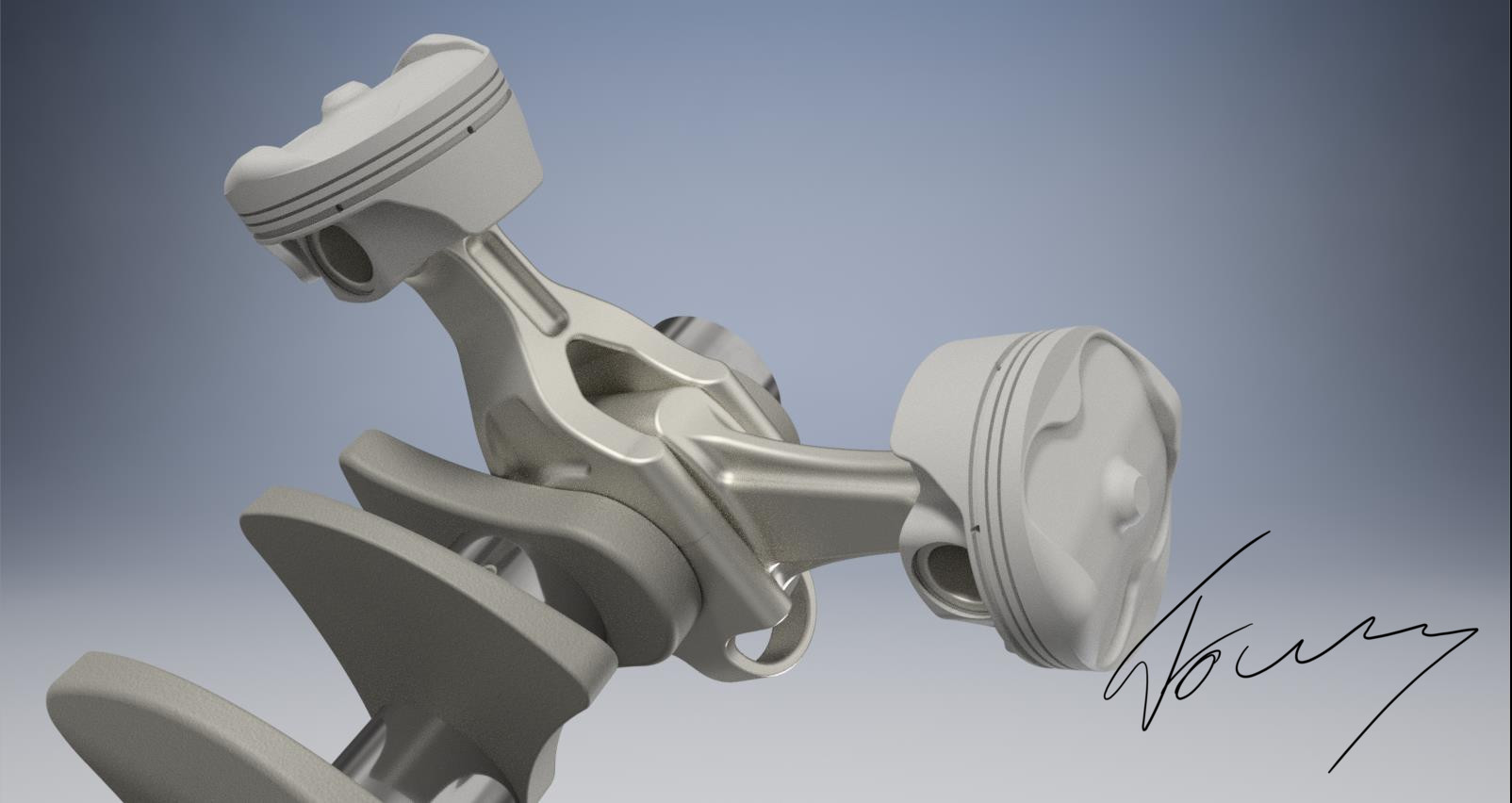
Here you can see two pics of how the Pistons and the rods are arranged:
Image
Image

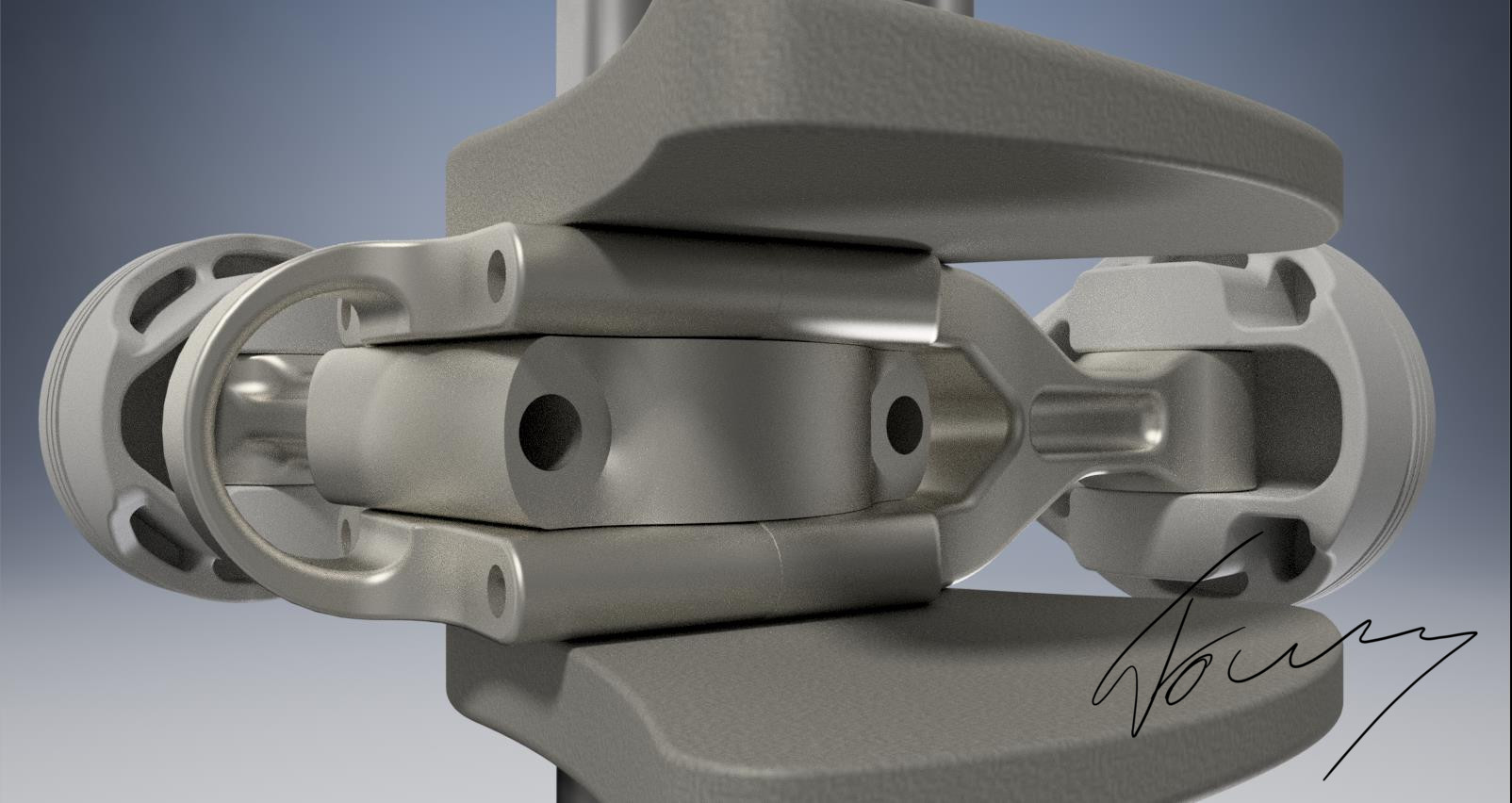
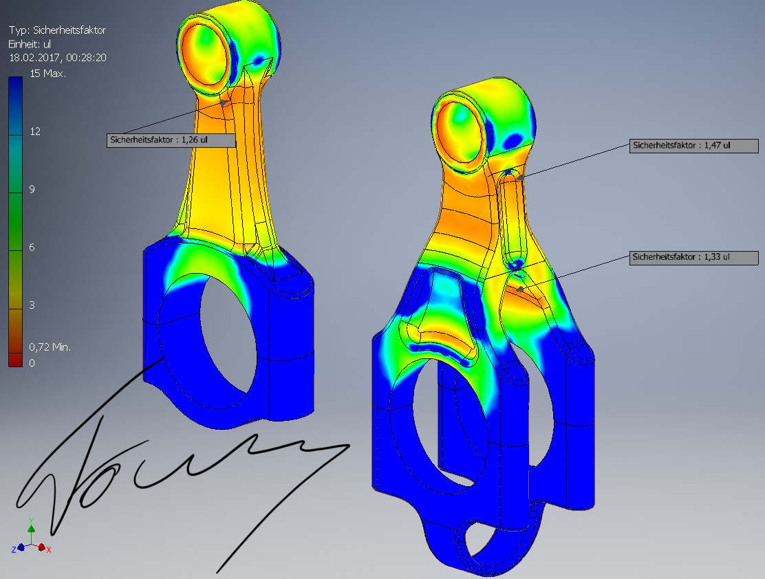
As you can see, the rods don't look very familiar. This is due to the different optimization of the single rods to improve stability and stiffness. The Rodcap of the forg-styled rod isn't seperated! The arc at the bottom allows to increase stiffness in the area of the bearing. Overall, the only difference between these two rods is that the forg-styled weighs approx. 30-40% more, so we have to compensate that a bit.

But because of the low center of gravity of the rod, this increased force is mainly radial force on the crankpin. Thank's to the positioning at the ends and the single rod in the center, this force also gets evenly distributed.

Regaring the bearings, the concept shown here uses one bearing for the single rod and two thinner ones for the forg-styled rod. The tolerances in between the inner faces of the forg-rod and the outer faces of the single rod can be made very thin, and thanks to the huge amount of oil going through this passage, These 2 contact points also could have some sort of dampening effect to the rods, which is - again - improving the pressure distribution at the outer bearings.


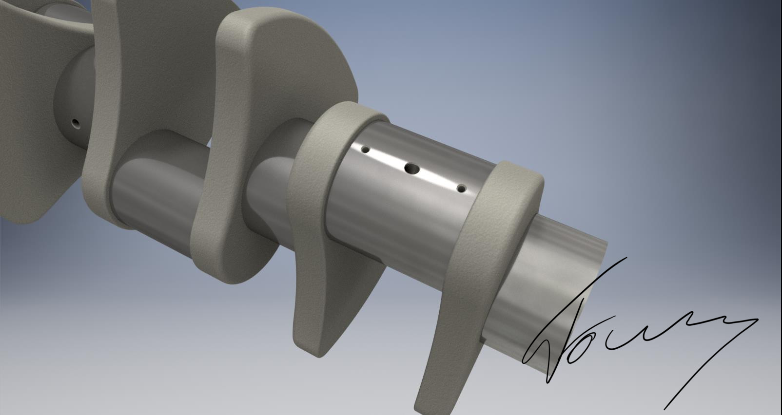
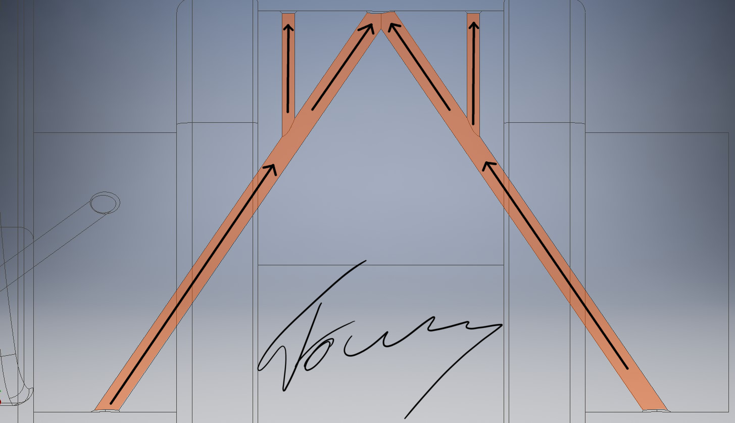
Now about the lubrication system. Of course, only having two bores down from both main bearings to the center points of the two halves of the crankpin isn't enough, as we have a total of 3 bearings and the oil-feeding bores would come out right between them, which is the worst position you could get for lubrication access :D

So, my idea was to make the traditional two bores right into the center point of the whole crankpin. Then, another two smaller bores on the center points of the forg-rod bearings are made. These bore Points could also be set a bit more outwards than directly in the center to further enhance lubrication at the "critical" outer points of the forg-rod bearings.
Image
Image


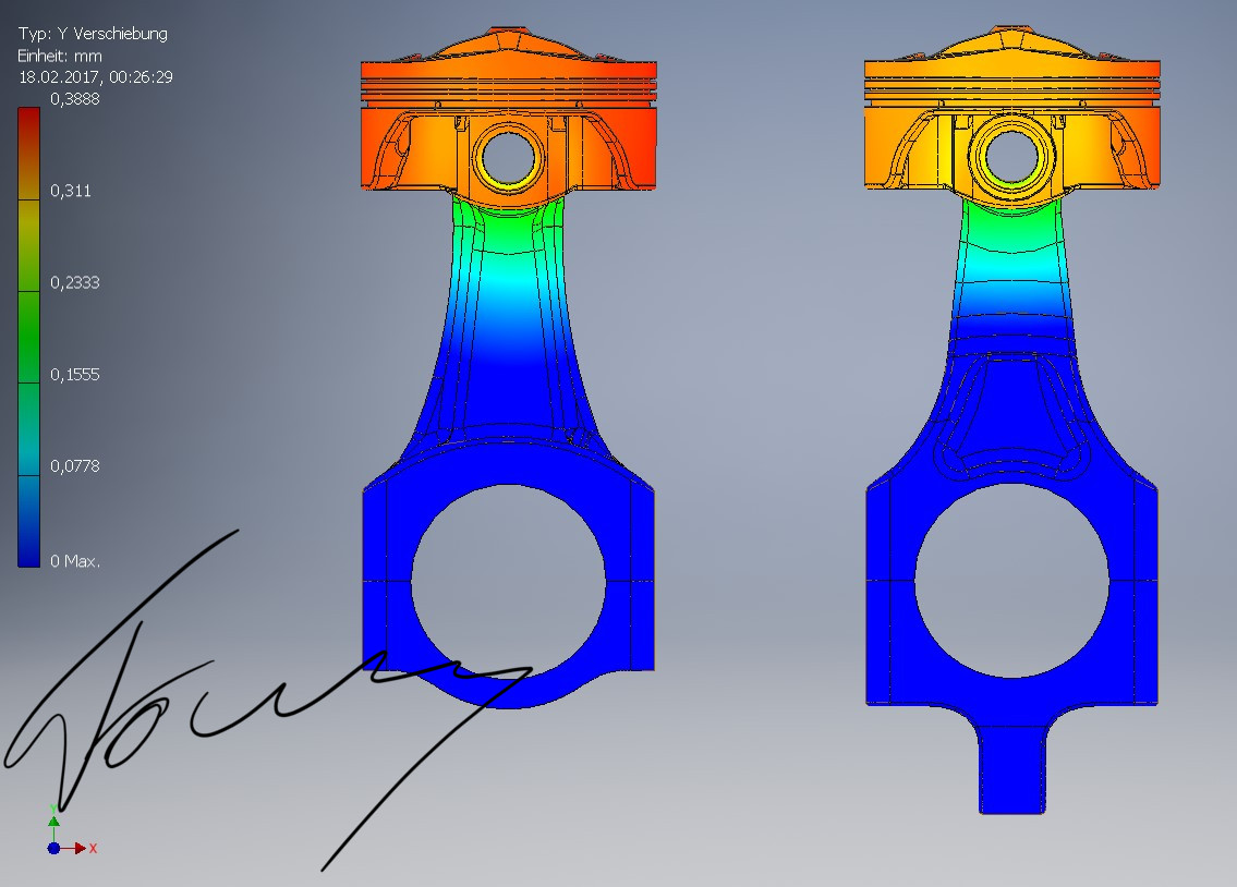
And I also have two screenshots of a FEM-simulation (38MPa cylinder pressure). While I did not took a look at the dynamics, the results look very promising! The stability on the seperation area is very good (while it still has potential to be further improved). What impressed me the most was the low amount of movement in this speration area. When looking at the screenshot with the amount of movement on the Y-axis, you can see there is no critical or important movement in the seperation area!
Image
Image

So, to conclude: After being critical, i do really think that the forg-styled rod could be a thing. The problems that come with it are manageable. Maybe you can see more in the pictures ;)
Last edited by glenntws on 18 Feb 2017, 10:30, edited 1 time in total.

wuzak
wuzak
467
Joined: 30 Aug 2011, 03:26

Re: Honda Power Unit

Post

Since you did the stress analysis, do you actually need the joining strap between to fork blade caps?

Is there much difference in the weight of the two rods?

Also, often in fork-and-blade rod systems the fork rods clamp to a bearing which runs on the bearing journal, while the blade rod runs on the outside of the centre part of the bearing.

wuzak
wuzak
467
Joined: 30 Aug 2011, 03:26

Re: Honda Power Unit

Post


roon
roon
412
Joined: 17 Dec 2016, 19:04

Re: Honda Power Unit

Post

Wazari wrote:1-4-5-6-3-2? 1-5-3-6-2-4? 1-4-3-6-2-5? 1-4-2-5-3-6? or 1-2-3-4-5-6?
This is a clue isn't it? Does Honda number their V's per bank or along the crank?

roon
roon
412
Joined: 17 Dec 2016, 19:04

Re: Honda Power Unit

Post

Interesting to note one of the reasons for layered bearings. The resulting increase in diameter around the journal provides more bearing surface area without making the blade wider.

In F1, the regs intend for the crank & rods to be monolithic. So they'd have to machine a diametrically larger step in the center of the journal to achieve a similar effect.

User avatar
godlameroso
309
Joined: 16 Jan 2010, 21:27
Location: Miami FL

Re: Honda Power Unit

Post

roon wrote:
Wazari wrote:1-4-5-6-3-2? 1-5-3-6-2-4? 1-4-3-6-2-5? 1-4-2-5-3-6? or 1-2-3-4-5-6?
This is a clue isn't it? Does Honda number their V's per bank or along the crank?
I think it's standard on all blocks since they have to turn clockwise, right bank looking from the front = 123, left bank 456.

Maybe it's different though.
Saishū kōnā

roon
roon
412
Joined: 17 Dec 2016, 19:04

Re: Honda Power Unit

Post

Thunders wrote:So after hearing that Clip 3 Times on 3 different devices (at first i thought my Headphones died ^^) my first reaction were the exact words as the Renault answer to that Video: (yes i realise it's because they posted their fire up Video too, but the comment was fitting)
https://twitter.com/RenaultSportF1/stat ... 4726253572
I have a feeling Honda have designed a monster. Renault ought be careful with their taunts. This could be the sound of their defeat.
Last edited by roon on 18 Feb 2017, 04:24, edited 1 time in total.

User avatar
Wazari
623
Joined: 17 Jun 2015, 15:49

Re: Honda Power Unit

Post

godlameroso wrote: I think it's standard on all blocks since they have to turn clockwise, right bank looking from the front = 123, left bank 456.

Maybe it's different though.
No it's not different.. :idea:
“If Honda does not race, there is no Honda.”

“Success represents the 1% of your work which results from the 99% that is called failure.”

-- Honda Soichiro

wuzak
wuzak
467
Joined: 30 Aug 2011, 03:26

Re: Honda Power Unit

Post

roon wrote:
Interesting to note one of the reasons for layered bearings. The resulting increase in diameter around the journal provides more bearing surface area without making the blade wider.

In F1, the regs intend for the crank & rods to be monolithic. So they'd have to machine a diametrically larger step in the center of the journal to achieve a similar effect.
I don't see any rules that would prevent the system used by Allison - bearing shell width same as overall width of fork rod, with bearing material on the outside of the centre of the shell for the blade rod to run.

User avatar
Thunder
Moderator
Joined: 06 Feb 2013, 09:50
Location: Germany

Re: Honda Power Unit

Post

roon wrote:
Thunders wrote:So after hearing that Clip 3 Times on 3 different devices (at first i thought my Headphones died ^^) my first reaction were the exact words as the Renault answer to that Video: (yes i realise it's because they posted their fire up Video too, but the comment was fitting)
https://twitter.com/RenaultSportF1/stat ... 4726253572
I have a feeling Honda have designed a monster. Renault ought be careful with their taunts. This could be the sound of their defeat.
Well to be fair their comment wasn't about the Honda engine sound but because they posted their own Soundclip almost at te exact same time. So that was the awkward part.

I just thought the wording perfect for what i felt after hearing the McLaren Clip for the first Time.

Sorry for the confusion.
turbof1 wrote: YOU SHALL NOT......STALLLLL!!!
#aerogollum

tok-tokkie
tok-tokkie
37
Joined: 08 Jun 2009, 16:21
Location: Cape Town

Re: Honda Power Unit

Post

On the forked con-rod. Could two narrow rods be used in place of the forked rod? It means different pistons for the single & twin rod cylinders. But is there room in the piston for the small ends of the twin rod cylinders? Then two straight rods so the twisting issue falls away.

glenntws
glenntws
87
Joined: 15 Feb 2017, 15:41
Location: Germany

Re: Honda Power Unit

Post

tok-tokkie wrote:On the forked con-rod. Could two narrow rods be used in place of the forked rod? It means different pistons for the single & twin rod cylinders. But is there room in the piston for the small ends of the twin rod cylinders? Then two straight rods so the twisting issue falls away.
Good idea, in combination with the bearing system someone has shown above, that could really work :) I try to do a model this evening.