DRD 2013

Here are our CFD links and discussions about aerodynamics, suspension, driver safety and tyres. Please stick to F1 on this forum.
shelly
shelly
136
Joined: 05 May 2009, 12:18

DRD 2013

Post

A thread to put images and comments specific to the DRDs of 2013 cars (till now Lotus, Mercedes and Sauber)

Good references:
http://scarbsf1.com/blog1/2012/09/13/me ... on-device/
http://thejudge13.com/2013/02/10/f1-for ... reduction/

My first impression is that saubers's solution resembles more closely a 2010 f duct (pipes sizes, no specific monkey seat, small ears) comapred to louts' and merc's.
twitter: @armchair_aero

Rikhart
Rikhart
19
Joined: 10 Feb 2009, 20:21

Re: DRD 2013

Post

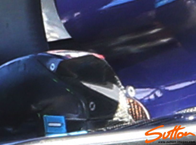
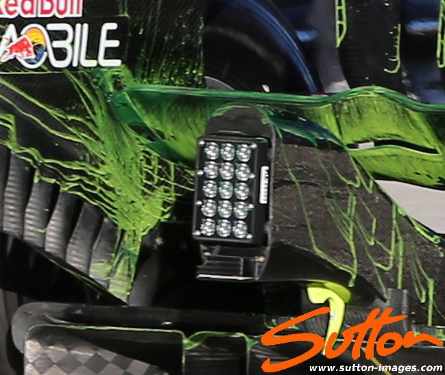
Redbull has a drd as well, that blows the beam wing. The intake is on the swan neck holding the beam wing.

Opening:

Image

Close up:

Image

Result on beam wing flowviz:

Image

User avatar
Blackout
1566
Joined: 09 Feb 2010, 04:12

Re: DRD 2013

Post

Edit Interesting

User avatar
ringo
230
Joined: 29 Mar 2009, 10:57

Re: DRD 2013

Post

So to kick things off. Anyone knows what the DRD does to reduce drag?
For Sure!!

Huntresa
Huntresa
54
Joined: 03 Dec 2011, 11:33

Re: DRD 2013

Post

ringo wrote:So to kick things off. Anyone knows what the DRD does to reduce drag?
In the tube itself there lives small magic fairys that magically reduce drag.

Kidding aside i dont think we will ever fully understand what it does unless someone actually explains it or an expert in the field that isnt in F1 takes a shine to it and experiments.

shelly
shelly
136
Joined: 05 May 2009, 12:18

Re: DRD 2013

Post

Which way do those fairies move their wands? up or down?
After the hypotesis on sucking instead of blowing for the lotus device, I thought a bit more and found that you can create a centrifugal pressure gradient (i.e. pointing ouside the curvature of the lower surface) either by blowing or sucking.
Taking as reference a device with the periscope exit pointing up (no lateral exits as on lotus e20) if you imagine a 2d slice in the center of the wing, and focus on the control volume delimited y the lower surface of the mainplane, the upper part of the periscope and two verical imaginary lines, you can have a rough example just applying conservation laws.
If you blow, you make a high pressure spot on the wing surface (high pressure balances the vertical momentum of the flow exiting the periscope; if you suck, the pressure at the face of the periscope is lower than the pressure on the wing surface.
So in both cases you can achieve the pressure gradient that forces the streamlines to detach.

The fluidic switch could be something similar to what was used on 2010 f-ducts with a pilot flow (but there has been no evidence of that yet) or be something different.
In my opinion a good way of tuning the mass flow in pipes is using meshes. If the cell size of the mesh screen is small, the premebility wich is dominated by the local reynolds number exhibits a significant variation - i.e for higher mass flow the drag coefficient is half or less. If there is a bifurcation inside the piping system and one branch is screens by a fine mesh and the other is not, the higher the mass flow in the pipes, the higher the percentage of mass flow through the screened branch.
twitter: @armchair_aero

User avatar
ringo
230
Joined: 29 Mar 2009, 10:57

Re: DRD 2013

Post

Ok before going to the fluidic switch let me take a whack at how the drd reduces drag in the first place.
From the F duct days, we have the wake control theory. I don't know where i can dig up that thread or the you tube video i made but any how. Wake control is the name of the game when unloading the wings to reducing drag.

The f1 wing is almost vertical, and the up-wash from the air flow around the surface is almost vertical as well. You notice this rooster tail when the car is driving in the wet. The size of the wake behind the wing has a relation to the drag of the car.
Naturally more downforce means a larger wake and also more drag.

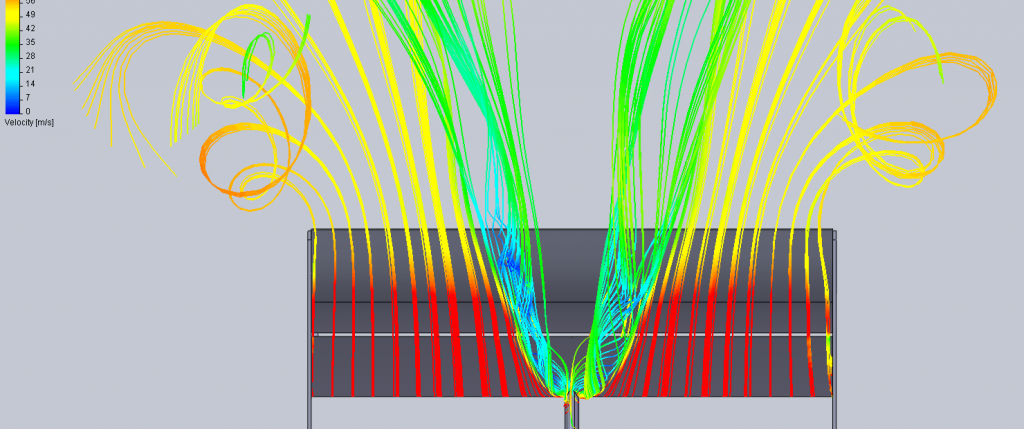
The drd is used to unload the weakest flow on the wing; the centre flow. This is probably how this flow looks when stalled:
Image

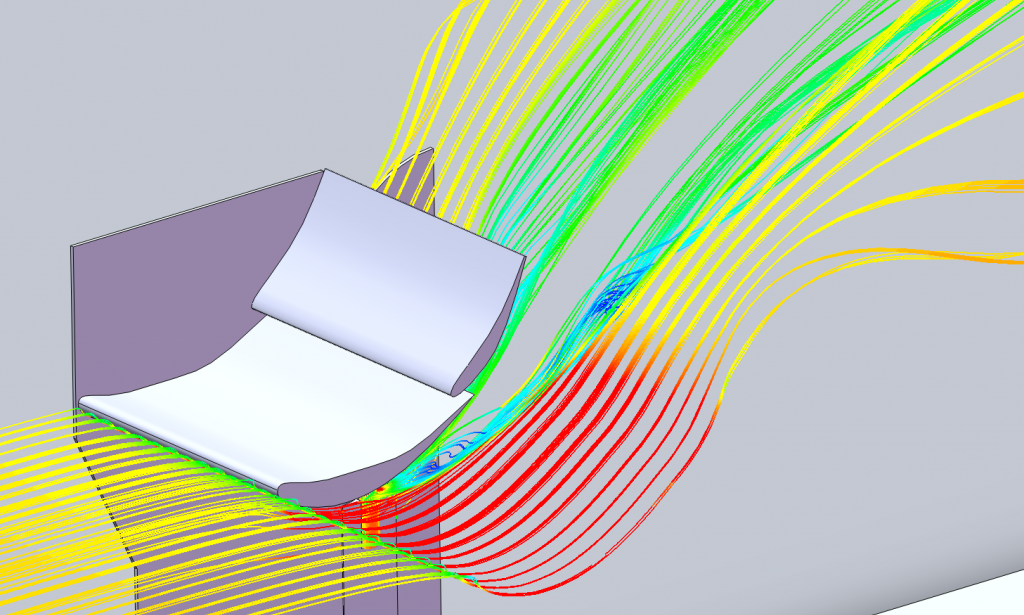
Air is blown through a pipe perpendicular to the flow on the wing. Blown just where the flow begins that upward climb round the back.There is roughly a 5-10mm gap between the wing and the tube. This air "collides" with the underflow, stripping it from the wings surface, detaching flow; if you will.
And what you see is the above results. Of course this air needs to have a certain amount of momentum to do this.
Image

Now how does creating this kind of separated flow reduce drag?
We know it unloads the wing, but drag reduction how?

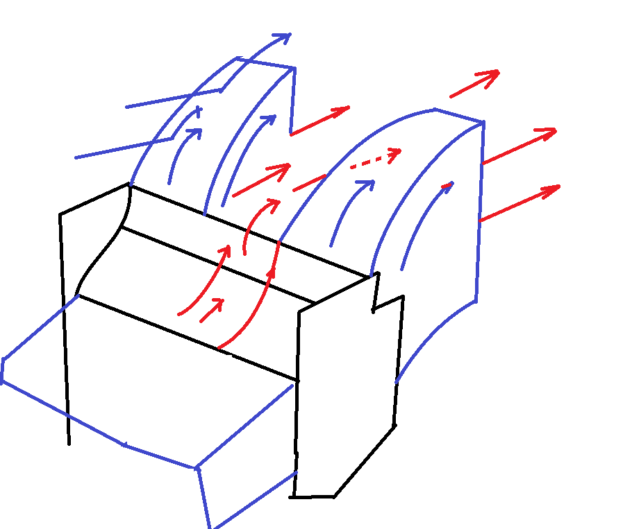
Well, if you notice that v in the middle. It's basically a hole where there is no upwash. Effectively the upwash volume is reduced by a sizable percentage. The "weir notch" is where flow from to top of the wing will deviate to, instead of taking that upward stream which would normally be the case if there was the typical upward momentum from the wing underflow in the center.
Image

Looking at the above, you can see the normal flows on the outside near the endplates. The arrows indicate flow direction.
You have your rear wing and the general flow and wake in blue. The red is the flow on the top side of the wing.
Notice how the V notch in the middle allows the flow to pass through, no longer taking the upward pathway like the flow on the outdide. It is this reduced wake size that gives that drag reduction. This is what happens when a wing unloads, the momentum of the airflow is reduced which is related to wake size. So they key is wake control.
Image
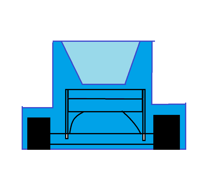
Soo... from the back, here is a representation of what is happening in a nutshell. The light blow is how much your wake size will be reduced. And we all know the relationship between area and drag. Smaller area, smaller drag.
Basically this is how i reason the drag reduction device. A stalled wing is a very draggy and inefficient wing, but and F1 wing, due to it's vertical momentum nature, will be have a drag increase in the region of the wing, but due to a smaller wake the drag reduction from the wake trumps the increase on the wing, resulting in an overall drag reduction.

And keep in mind this is what i think, it is not verified.

To add to this, if you can allow that V to broaden the drd will be more effective. The wing shape from sauber is suggesting that the curvature underneath is there to make the effect spread out a little more.

On the topic of increasing drd effect, you can also say that having two pipes or "elephant trunks", would create 2 super imposed Vs further reducing wake size wouldn't you think?
For Sure!!

User avatar
hollus
Moderator
Joined: 29 Mar 2009, 01:21
Location: Copenhagen, Denmark

Re: DRD 2013

Post

As in everything aero, that's one way to look at it. Thanks for a nice post, Ringo.
I would challenge the interpretation that the air wall is directly causing the drag by increasing the cross section of the car. Once that air has left the rearmost tip of the rear wing, I don't see how by blocking the free air stream it can affect the car, or at how it can cause significant drag.

In my opinion the air wall is an effect, and not the cause, of the drag created by the wing. To try to support this, I'll look at the rear wing from a Newtonian point of view:

The rear wing is pushing air upwards, that much is obvious. If this was done by simply adding vertical momentum to the incoming air, the air would actually gain total speed and our wing would be an energy producing machine. I'll assume that this is not the case, and the wing is simply redirecting the air, effectively turning horizontal momentum into vertical momentum, as shown below (where all arrows are the exact same length). Then the air wall appears as the consequence of having turned the air, and turning the air itself causes the drag by transferring horizontal momentum (backwards) from the air to the car.
In this interpretation, the stall is simply reducing the effectiveness of the wing by rendering part of it useless, so that air is turned to a lesser degree by the wing overall.

Image

Of course there is the barn door in the air stream component of drag, buy I would contend that this is already being paid equally by the normally functioning rear wing.
A CFD test comparing a standard rear wing to a barn door wing (a flat plank diagonally filling the wing's legality box) would probably be most illustrating.
Last edited by hollus on 03 Mar 2013, 14:57, edited 1 time in total.
Rivals, not enemies.

User avatar
raymondu999
54
Joined: 04 Feb 2010, 07:31

Re: DRD 2013

Post

I'd just like to discuss activation mechanisms for a bit.

Most sources around say that the DRD should be controlled by a pressure switch, to be activated above a certain velocity. I was looking back at photos of the 2010 fducts, and it reminded me how many people were criticising that the Merc airbox back then could suffer circulation under extreme yaw - as some criticised the McLaren L-pods in 2011 too. Would it be possible, instead of doing a speed - based activation mechanism, to do a direction based mechanism, based on a speed differential? For example, the Lotus has two ears anyway - would it not be possible to activate the DRD using such directional measures? In the case of a big enough differential between the two ears, obviously the car is at yaw, and deactivate the DRD?
失败者找理由,成功者找方法

Rikhart
Rikhart
19
Joined: 10 Feb 2009, 20:21

Re: DRD 2013

Post

raymondu999 wrote:I'd just like to discuss activation mechanisms for a bit.

Most sources around say that the DRD should be controlled by a pressure switch, to be activated above a certain velocity. I was looking back at photos of the 2010 fducts, and it reminded me how many people were criticising that the Merc airbox back then could suffer circulation under extreme yaw - as some criticised the McLaren L-pods in 2011 too. Would it be possible, instead of doing a speed - based activation mechanism, to do a direction based mechanism, based on a speed differential? For example, the Lotus has two ears anyway - would it not be possible to activate the DRD using such directional measures? In the case of a big enough differential between the two ears, obviously the car is at yaw, and deactivate the DRD?
Wouldnt that render the wing "stalled" for braking etc? Since they brake in a straight line, this would be undesirable because you want lots of downforce when braking, right?

User avatar
hollus
Moderator
Joined: 29 Mar 2009, 01:21
Location: Copenhagen, Denmark

Re: DRD 2013

Post

I would be indeed possible, but remains for now a theory in fantasy-land. (Thanks to Zonk for highlighting that when off the throttle, the airbox would be ingesting less air, and likely causing spill-over, and I know that you have a different theory about the relation between those ears and the spillover).

Edit: This is supposed to represent the Lotus E21, with the ears significantly trailing the central engine's airbox.

Image
Last edited by hollus on 01 Mar 2013, 17:39, edited 1 time in total.
Rivals, not enemies.

User avatar
raymondu999
54
Joined: 04 Feb 2010, 07:31

Re: DRD 2013

Post

Rikhart wrote:
raymondu999 wrote:I'd just like to discuss activation mechanisms for a bit.

Most sources around say that the DRD should be controlled by a pressure switch, to be activated above a certain velocity. I was looking back at photos of the 2010 fducts, and it reminded me how many people were criticising that the Merc airbox back then could suffer circulation under extreme yaw - as some criticised the McLaren L-pods in 2011 too. Would it be possible, instead of doing a speed - based activation mechanism, to do a direction based mechanism, based on a speed differential? For example, the Lotus has two ears anyway - would it not be possible to activate the DRD using such directional measures? In the case of a big enough differential between the two ears, obviously the car is at yaw, and deactivate the DRD?
Wouldnt that render the wing "stalled" for braking etc? Since they brake in a straight line, this would be undesirable because you want lots of downforce when braking, right?
Fair point. Traction too, now that I think of it. It would be a laptime hindrance in the wet.
失败者找理由,成功者找方法

shelly
shelly
136
Joined: 05 May 2009, 12:18

Re: DRD 2013

Post

I have been looking at 2010 f-duct picture also, and what I noticed is that the passive device merc ran that season was so small that it was completly housed in the rear mainplane (if the hypotesis of that time were correct).

From 2010 the no slits are allowed in the wing profiles, thus spoiling the downforce cannot achieved directly by a jet spoiler like they did in 2010; but besides that, why does 2013 passive device on merc have to be so much bugger than 2010?

Most reasonable idea is thet, being the easiest spot for disrupting flow now forbidden, acting from elsewhere requires more powerful flow.

http://i.imgur.com/dHAA5FU.jpg

I have noticed that lotus periscope is positioned quite at the back, below the upward sloping part of the mainplane
twitter: @armchair_aero

User avatar
amouzouris
105
Joined: 14 Feb 2011, 20:21

Re: DRD 2013

Post

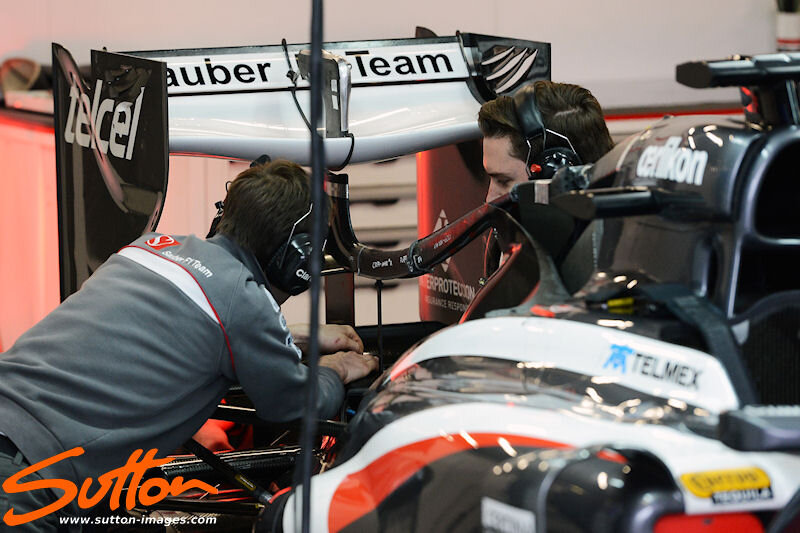
Since we have the basic idea of how the Lotus & Merc systems are activated. I would like to discuss how the Sauber and RB systems are activated. Both the Sauber and RB are missing the curved monkey seat with the pipe underneath.

I do have an idea of how it could work, but I dont know whether it will work or not. It involves the airbox as the switch. and an f-duct like cross-(road).

I got this idea when looking at the sauber with the engine cover removed. Basically, the air coming from the 'ears' is actually directed elsewhere first. You can see a pipe curving down on the sauber. Above a certain speed when the engine does not need all the air coming inside the airbox it would bleed it outside. On the sauber, instead of bleeding it outside, it is directed to the cross-(road) directing the flow from the ears to the vertical tube and stalling the wing.

This is pure speculation however. I don't know if such a system would actually work.

In addition, what would happen when the engine is not actually on the intake stroke, and the intake valves are shut?

My thoughts need some fine tuning

Edit: Can someone dig up the Sauber DRD piping photo pls?

Edit 2: Found it!
Image
Last edited by amouzouris on 01 Mar 2013, 23:26, edited 1 time in total.

Absolutelee
Absolutelee
1
Joined: 05 Jun 2012, 01:55

Re: DRD 2013

Post

Does anyone have an idea how the switch actually works? I'm imagining a door with a variable force spring holding it closed, but I'm assuming it is more complicated than that in reality.