I'm interested in learning more about F1 Body Design. I have 2 specific questions that I have been contemplating, however as F1 secrets are kept under lock and key, it is difficult to find answers online. I would greatly appreciate any advice from anyone involved in F1 as a CAD Engineer or Aerodynamic Designer.
Question 1: I know that aerodynamic performance is one of, if not the top factor considered in modern F1 Car design. I was wondering if cars were designed as a water-tight CAD body and then hollowed out for the internals, or if the internals were made first and then wrapped in a body surface (see image 1 below)
Question 2: I have been developing my CAD skills and understand sweeping profiles along splines to make organic shapes (eg. front wing elements). However, I am unsure as to how I would go about designing the sidepods and engine cover. The approaches I've seen online seem insufficient for generating the complex curvatures/interfaces seen on modern F1 bodies (see example image 2 below). All of the Aero Designer job postings I see ask for skills with Surface Modelling / Wireframe design. Does anyone have a high-level example (with images) to show how a modern F1 body is modelled in CAD?
I think my first advice is don't use something I made 7/8 years ago when onshape was a solid body modelling only tool as an example
You will not find much online about modern F1 cars - because teams want to keep that in house. Mark Lane - ex-alpine/renault / mclaren surfacer has been posting some stuff but it's probably too far advanced for what you're asking - i.e. all finished surfaces rather than starting from scratch. https://www.linkedin.com/in/marklane5/r ... ivity/all/
Also ex-F1 people won't want to give their advice for free. They gotta pay the mortgage. B-sport recently did a video on youtube about adding a shedding edge to a wing, while I'm not a particular fan of the way it was modelled, plus there's some legality concerns in the region he modelled which he completely ignores, it's at least something to show the surface-spline-surface approach.
The best advice (that I'm willing to share) I've ever been given from a surfacer is to break things into "slabs" and "blends", i.e. big overlong surfaces with a nice low degree of curvature, which incrementally gets broken/refined with increasingly higher curvature elements. Slabs can be created from a sketch or a spline on points, and can be 2-d (i.e. single curvature) or 3-d (compound curvature).
You can see on the Caterham example that's how they worked. The sidepod has a side face, a top face, and a radiused corner. Similarly the engine cover has a side face which is then moslty eaten by a blend to the centreline and the fillet to the cooling exit.
#aerogandalf "There is one big friend. It is downforce. And once you have this it’s a big mate and it’s helping a lot." Robert Kubica
I am not an F-1 CFD, just a hobbyist, but have done a few on this site long ago. It's easier to make the solid model.
I learned the hard way by modelling the panels as actual panels. This created problems when meshing and simulating for CFD.
Best to model the body as a solid block and create recessed faces representing the openings. Apply boundary conditions to the faces that represent as close as possible what you think the flow in the opening is.
From your results, you can then create new detailed models to investigate in detail.
As for the organic shapes, you can slice up your design into plane profiles then use splines to connect them. Then sweep them after. There are cases why fillets and intersecting bodies may be the best thing to do to get what you want. But you have to experiment and see what's best.
I did a little more digging based on your suggestions. I found some of the MVRC cars on OnShape to examine, as well as some of the images posted by Mark Lane.
I haven't found a definitive answer to my first question as to whether designers typically start with a CFD Solid and then hollow out the body for the internals, or if they start with internals and then wrap them with a body, but I think I've concluded that the approach doesn't necessarily matter as long as you get to the final result that you want.
The Body Legality Limits are fairly prescriptive, setting the outward limits to the body shape/size, and the inner components/systems set the inward limits.
My current thought it that surfaces are used instead of solid bodies since organic shapes are more easily modelled using splines and surfaces. Also, over building surfaces and trimming them would likely allow for greater flexibility in terms of parametric modifications.
I would still very much appreciate if anyone with first-hand experience could validate those assumptions. In the meantime, I will get started practicing!
You can model the organic shapes just as well with solids. The solids will just be defined by the splines.
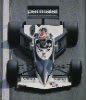
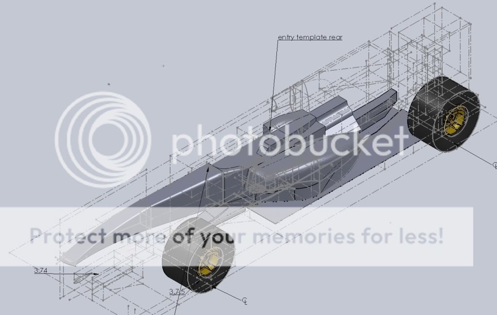
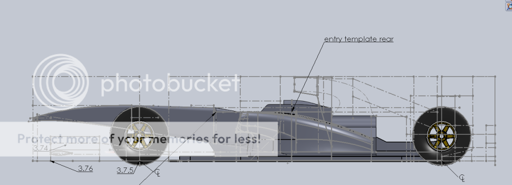
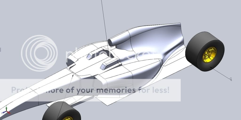
I found some of the old images using Goolge. I thought they were lost after photobucket ended. As you can see this may have been a solid model. Started out as surface then changed. This was back in high nose F-1 car days. The finished product is lost to the internet I guess.
Ringo's 1st post was my approach also, solids in the beginning which only gets you 60% done.
Convert all solids to surfaces, slice, weave splines, 100hrs will see a fine model drawn.
If you are lazy and want to cheat,
Find a gaming website that distributes mesh models, convert from .obj to .dxf and you end up with a skeleton of triangles, use this for weaving your splines and building surfaces.
In real f1 terms this would result in a display car at best, you still need cfd to qualify your shapes.