Monocoque chassis
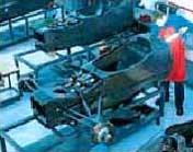
The tub must be able to withstand the huge forces produced by the high cornering speeds, bumps and aerodynamic loads imposed on the car. The tub is first designed on a Computer Aided Design (CAD) package and from these designs, a computer controlled machine cuts pieces of ureol to make a mock up from which a mould is made.. This material is not unlike wood, but is man-made and does not absorb water. It is also grain less and does not expand under temperature and so a very accurate model of the chassis can be made. This chassis model is then covered in carbon fibre to create a mould from which the actual chassis can be made. Once produced the mould is smoothed down and covered in release agent so the carbon-fibre tub can be easily removed after manufacture.
 |
 |
The mould is then carefully filled inside with layers of carbon fibre. This material is supplied like a typical cloth but can be heated and hardened. The way the fibre is layered is important as the fibres can direct stresses and forces to other parts of the chassis, so the orientation of the fibres is crucial. The fibre is worked to fit exactly into the chassis mould, and a hair drier is often used to heat up the material, making it stick, and to help bend it to the contours of the mould. After each layer is fitted, the mould is put into a vacuum machine to literally suck the layers to the mould to make sure the fibre exactly fits the mould. The number of layers in the tub differs from area to area, but more stressed parts of the car have more , but the average number is about 12 layers. About half way between these layers there is a layer of aluminium honeycomb that further adds to the strength.
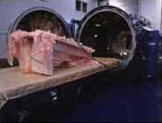
Once the correct number of layers have been applied to the mould, it is put into a machine called an autoclave where it is heated and pressurized. The high temperatures release the resin within the fibre and the high pressure (up to 100 psi) squeezes the layer together. Throughout this process, the fibres harden and become solid and the chassis is normally ready in two and a half hours. The internals such as pedals, dashboard and seat back are glued in place with epoxy resin and the chassis painted to the sponsors requirements.
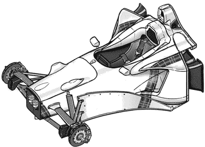
The fuel tank, or 'cell', is located immediately behind the drivers seat, inside the chassis. The cell is made from two layers of rubber, nitrate butadiene, with the outer layer being Kevlar reinforced to prevent tearing. The cell is like a bag, it can deform without tearing or leaking. The cell is made to measure exactly and is anchored to the chassis to prevent it moving under the high g-forces. The inside of this tank is very complex and contains various section to stop the fuel sloshing around, and there are up to three pumps sucking out the fuel so to get every last drop. These pumps then deliver the fuel at a constant rate to the single engine fuel pump. The link between the fuel tank and the engine is a breakaway connection so that the fuel flow is stopped automatically if the engine is ripped off the chassis in a large accident. Size of fuel tanks vary, but Jordan's fuel cell holds 135 litres. The picture below shows the tub complete with front suspension:

