ok, had a go at some CFD on the
nose cone idea. now before i start i will say that this is the first time i have done any cfd, i only started studying it 2 weeks ago!
this was a fairly brash and rough 1st attempt to prove to myself that i could create a 3d model and then import it to do some cfd on it!
1st image, this shows the pressure distribution, blue represents lower pressure areas and therefore the locations of down force generation.
i am aware of some "errors" in the plot where for some reason some grids haven’t been calculated properly and are therefore white.

it seems the extra
nose slot in my example actually has higher local pressure, so would therefore not be beneficial in this case i feel. Please give me suggestions of redesign to the "
nose slot" profile and i will try them again and see if it can be made to accelerate the flow. Also my front aerofoil sections are very rough i know, any suggestions there will be good too thanks.
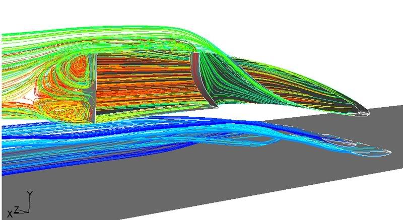
this, the 2nd picture, shows the velocity profile around the
nose. The cfd was done at 80m/s! Which is quite fast i realise, about 180mph or 288km/h.

again the airflow in the "
nose slot" does not accelerate, therefore i feel produces little effect.
the only thing that my be good is the reduction in "blockage" of the airflow behind the middle-rear section of the leading wing, therefore making it more effective perhaps.
interesting idea, i have some of my own, expect more soon.
until then, please give any feedback, +ve or -ve, i need to learn!


. They really trust in you


