SUSPENSION
I've decided to put an interconnected suspension on the
car. Its one of the few major complications that I'm adding to the
car because I think I can (and have already) learn a lot from its development. And also because racecar.
The main point of any interconnected suspension is to have a better control of the model stiffnesses. The typical targets (or the reasons for adding the complication of an interconnected suspension) are one or more of the following:
- Reducing the warp stiffness while maintaining roll and pitch stiffness
- Increasing vertical stiffness for downforce while maintaining roll, pitch and warp stiffnesses'
The effects of warp stiffness is something that I am currently researching. Generally warp inputs to the suspension come from the road in the form of road geometry (banking, twist or camber) or road irregularities. In this case, any warp stiffness changes the tyre loads due to these inputs. I have also seen that these warp inputs have a big effect on the load transfer distribution and therefore the balance of the
car. I personally consider this a bad thing because these road inputs are largely random - or at least inconsistent corner to corner. If you are able to reduce your warp stiffness, you will have a much better "disturbance rejection" characteristic of your suspension. I.e. it will not change the load transfer distribution due to random road inputs.
At which point I'd like to address Dave's concerns:
DaveW wrote:Forgive me, but I think that the idea of maintaining zero warp loads for an off-roader slithering around on mud might be a good idea, but not for a race car negotiating a circuit...
...I think that religiously maintaining zero warp loads though a corner would not be a brilliant idea.
While I do agree that different vehicle states call for different vehicle balance, I don't believe a passive warp stiffness is the right way to do it. As I have mentioned above (and as I show below in my linear model) any warp stiffness puts your balance at the mercy of random road inputs. An ACTIVE warp control on the other hand - that would be very useful as you have already seen.
Another type of warp input comes from steering geometry. If you have a non-zero kingpin angles and trails (in front and side view), your wheels will want to move up and down with respect to the body when you steer them. However, given that they are effectively fixed to the ground by the weight of the
car, instead you see a steering induced load transfer on the front axle which is opposed by an equal and opposite load transfer (assuming equal track widths) on the rear. This is effectively a warp load generated by the warp stiffness of the suspension. And given that its something connected to the steering it could also be something that the driver will feel. In this case the warp load variation is DESIGNED into the suspension as a function of the steering angle. In this case it COULD be desirable and at the least its CONTROLLED (as oppsed to the random road inputs) - Regarding the driver feedback, I have read reports of soft-warp suspensions having bad driver feedback which could possibly be due to this missing ride-steer effect.
To understand the role of the interconnected suspension I have built linear vertical model which simulates practically any type of 4 wheel independent passive suspension by representing it as a 4x4 stiffness matrix. The stiffness matrix is "attached" between the chassis (having pitch, roll and vertical degrees of freedom) and 4 wheel bodies each having 1 vertical degree of freedom. The wheel bodies attach to a mathematical "4 poster rig" via a vertical tyre stiffness. Other effects included are lateral/longitudinal jacking forces, sprung and unsprung weight forces and downforce. In total its a 7 degree of freedom steady state model. Basically a virtual 7 poster rig like this:
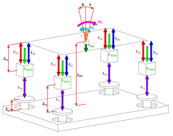
Through building this model I was able to setup a standard set of loadcases and see how the body movements and contact patch loads react. Of particular interest to me was how to reduce the warp stiffness while maintaing the same pitch and roll stiffnesses.
To facilitate this I have developed a couple of interconnected suspension concepts. One which allows independent definition of 3 of the principle suspension modes (vertical, pitch and roll - VPR) and one which allows independent definition of 2 of the principle suspension modes (pitch and roll - PR). Both of these solutions have a nominal zero warp stiffness BUT they have completely controllable roll stiffness distribution.
The VPR system translates the vertical wheel movement to a centre module via 4 master-slave cylinder pairs. The centre module is basically 2 cross beams (in blue) which are able to slide (left and right in the diagram) and rotate in the plane of the page in order to follow the 4 wheel movements. Here is the schematic along with the stiffness matrix (note that there are no zero elements - everything is fully connected).
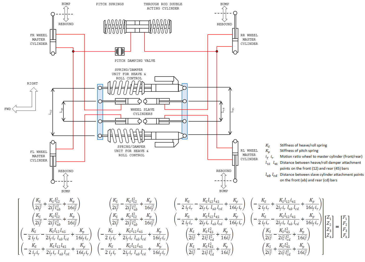 Hi-res
In 4 wheel heave, all 4 slave cylinders contract and pull the two beams together. Therefore the vertical stiffness is set by the stiffness of the 2 heave/roll spring-damper units which work in parallel. In roll the 2 beams rotate in opposing directions, deflecting the heave/roll springs. In this way you can set the roll stiffness and distribution by altering the spacing between the damper attachment points on the front and rear beams. The pitch stiffness is added via another spring which runs from a seperate hydraulic circuit linking the 2 front and 2 rear wheels to act on the pitch spring. In warp the 2 beams rotate like a parallelogram and the pitch spring doesnt work at all, so this is the reason there is no warp stiffness.
All in all, its quite a complicated system. The beams require complicated sliding prismic joints with a rotational pivot to allow roll movements.
The PR interconnected system is a bit more elegant and probably will be the one I decide to use. Like the previous system the wheel movements are transferred to a centre module using 4 master-slave cylinder pairs. Each slave cylinder connectes to a bell crank in the centre module. In the hydraulic circuit I have put in 4 damping valves into the hydraulic circuit to fix the lack of warp damping which is typical of soft warp suspensions. Without warp damping you will not be able to control the wheel mode resonances (in the range of 20Hz) which occur over rough roads. To make these I plan take the piston + valves from a normal damper and put them in a housing which is plugged into the hydraulic circuit. Here is the schematic and the stiffness matrix. Note here the zero elements for diagonally opposite wheels meaning they have no effect on each other.
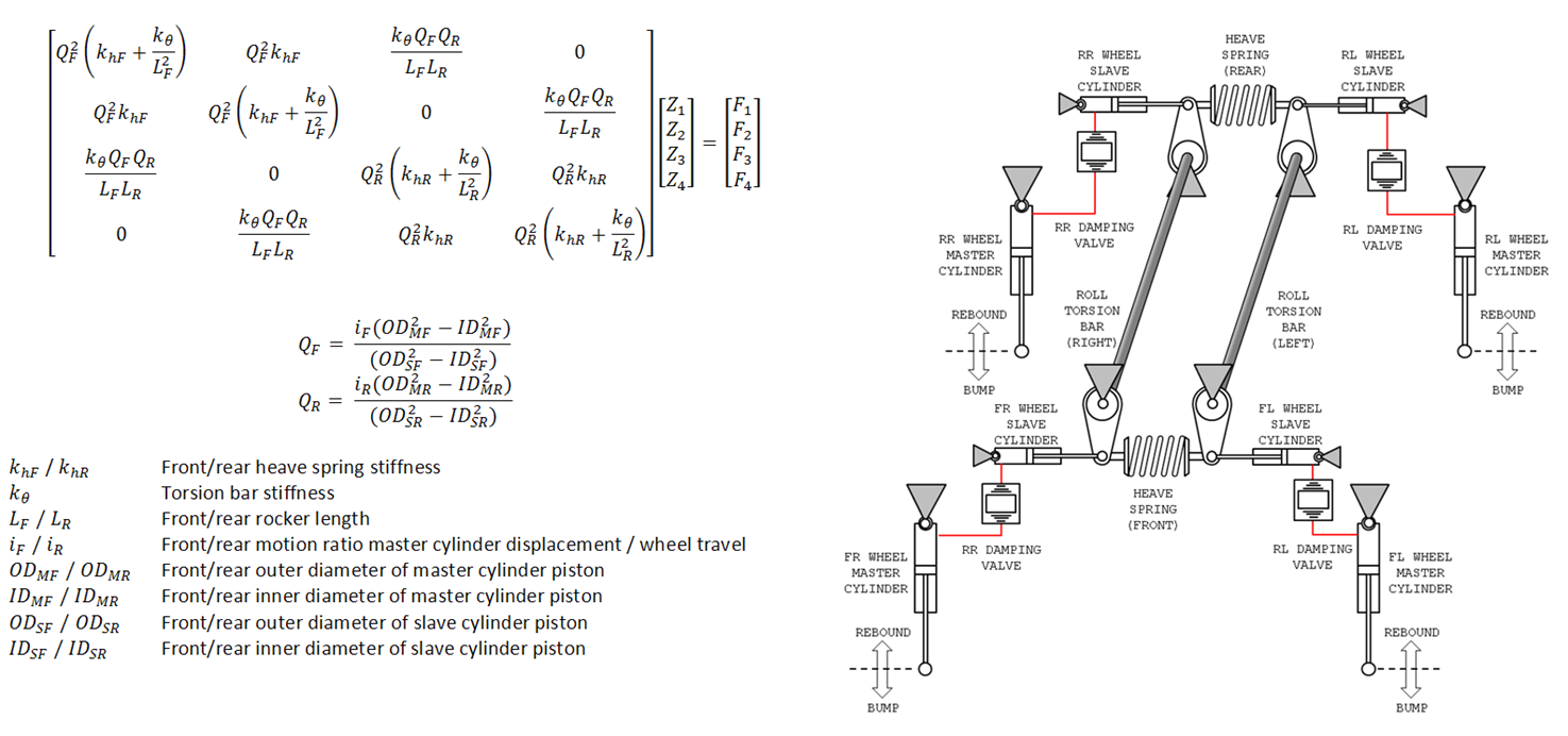 Hi-Res
The centre module consists of 2 torsion bars and 2 conventional springs connected to the bellcranks. The functionality should be quite obvious from the schematic. In pitch, the front and rear heave springs work like a 3rd spring on an F1
car and the torsion bars do not work at all. In roll it is the contrary - the torsion bars on the left and right twist and the heave springs don't work at all. Pitch stiffness is set by the front and rear heave spring stiffness', the roll stiffness is set by the torion bar stiffness' and the roll distribution is set by adjusting the bellcrank length.
Still reasonably complicated, but with less parts and joints compared to the VPR system.
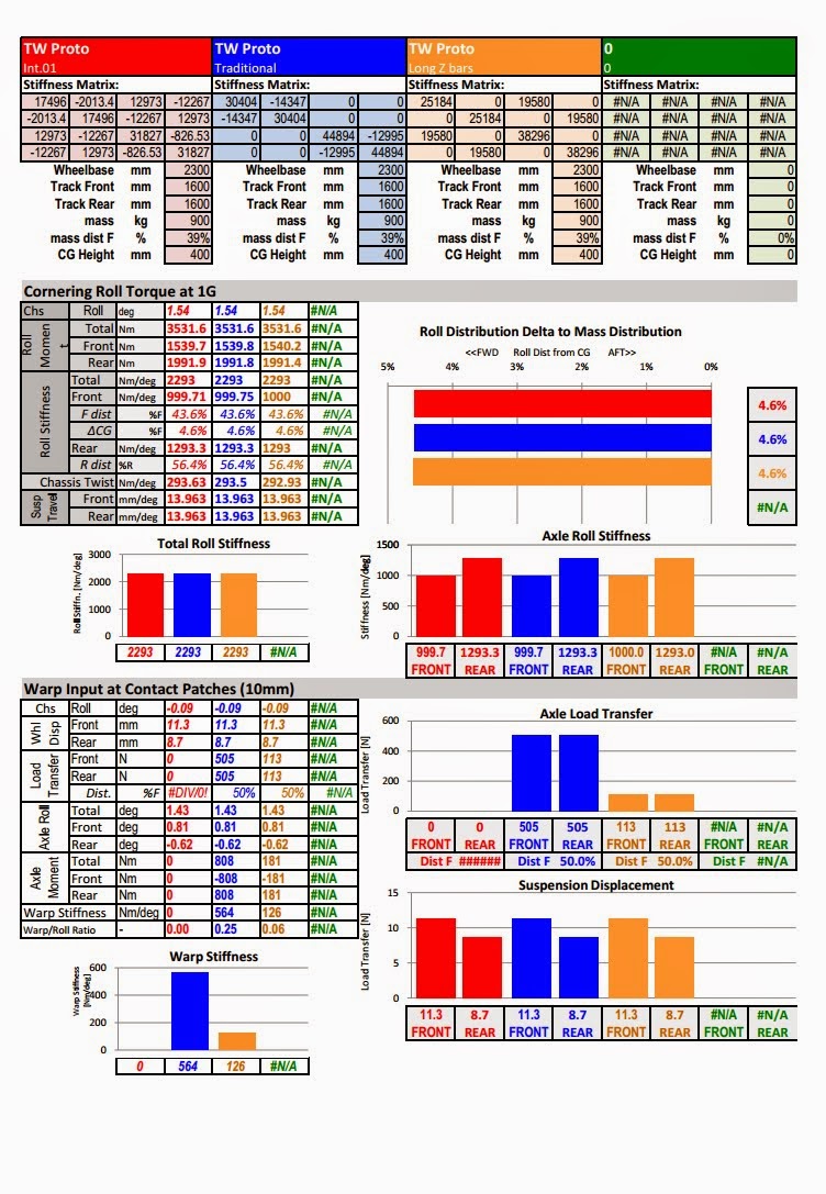
To investigate the two interconnected suspensions I have setup the following 3-way comparison in my model:
Vehicle 1: Traditional suspension (4 springs + ARB's)
Vehicle 2: Interconnected vertical, pitch and roll - VPR
Vehicle 3: Interconnected pitch and roll - PR
All suspensions were setup to give:
Roll gradient of 1.64deg/G
LLTD 43%
Pitch gradient braking: 0.6deg/G
Pitch gradient acceleration: 0.8deg/G
The traditional and VPR interconnected suspensions were also unified in their vertical stiffness'
Front frequency: 2.00Hz
Rear frequency: 2.20Hz
The VP interconnected suspension is not able to independently specify the vertical stiffness. It is instead related to the pitch and the roll stiffness. Actually a traditional suspension has the same constraint. Once you set the vertical wheel rates, your pitch rate cannot be specified independantly. The only suspension here which allows completely independent specification of all of the modes (except warp which is zero) is the VPR interconnected system.
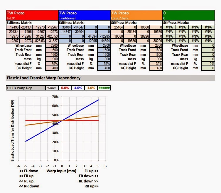
In cornering, all of the suspensions have the same roll gradient and load transfer distribution - but the main difference is the warp load rejection of the interconnected suspesnions. In the bottom diagram you can see the the interconnected suspensions maintain a constant load transfer distribution as the road is distorted in warp by +/-5mm. Instead, the traditional suspension changes its LLTD by +/-17% which is massive. To put that into context, when you make a spring or anti roll bar adjustment on a conventional
car, its effect on the LLTD is normally in the range of 0.5% - and a driver will feel this effect. Here, we can see that every mm of road imperfection changes the LLTD by 3.4% for the traditional suspension. So its orders of magnitude larger than what the driver is sensitive to.
 Hi-res
Also visible above is the force variation of the wheels in response to a 5mm impact (fixed chassis) and release (free chassis) of the front left wheel. The main point to note is that the load variation of the 2 interconnected suspensions goes to zero as the body responds, whereas the traditional suspension sees a parmanent load change of about 50N on each wheel which is another illustration of the disturbance rejection advantage of the interconnected suspensions. Also apparent is one possible disadvantage of the PR suspensions stiffer vertical mode - during the impact event (before the body responds) there is a much larger total load variation at the tyres.
In pitch there is not much of a difference in performance. I did notice that once you add in an interconnected suspension the classical formulas for determining anti-squat/lift/dive/raise are no longer valid...
 Hi-res
The vertical response shows only that the PR interconnected suspension is unable to match the same vertical stiffness of the tradional and the VPR interconnected suspension. The main reason for this is that the 2 springing systems (heave spring and torsion bars) work together in parallel in 4 wheel heave. Whereas in roll and pitch only 1 springing system is working. So in 4 wheel heave, you have the simultaneous sum of the roll and the pitch stiffness' which therefore gives you a vertical stiffness about 2 times that of the traditional suspension.
If this is good or bad is not clear. In terms of load variation a stiffer suspension is a bad thing. However a suspension which is stiff vertically while mantaining a lower roll and pitch stiffness allows you to have enough vertical compliance to minimise load variations but still be stiff enough to resist the high aerodynamic loads (diagrams on the right). In my opinion, the banned FRIC systems would have been doing something like this - which is consistent with the remarks from some of the F1 engineers that they had to increase the ride heights after the FRIC ban.
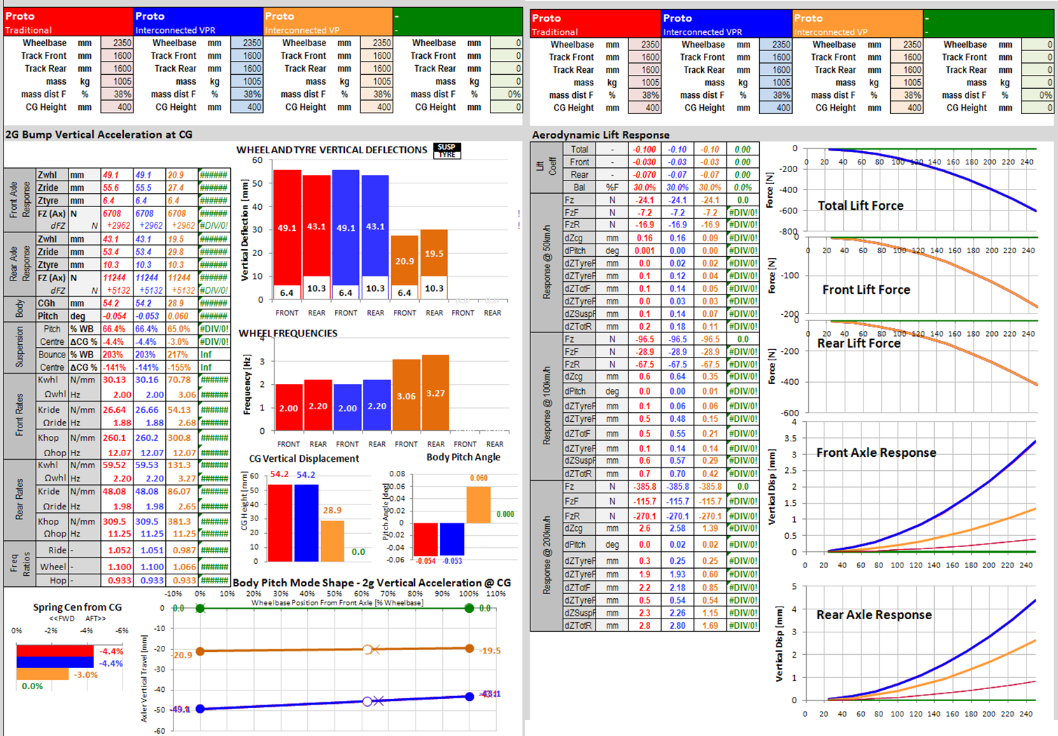 Hi-res
At the moment I am strongly leaning towards the PR interconnected system because its simpler to make and has less joints to introduce free-play and noise into the system. I may try to deal with the stiffer vertical mode by using non-linear pitch springs which are soft initially (for impact absorption) and then become harder to control pitch and vertical movements. One nice aspect of doing this with the front/rear heave springs is that it does not introduce non linearities into the roll distribution.


