You write:
“Thanks for the discussion.
No need to reply.”
Thanks for the proposal, but I will reply.
You also write:
“One error is the way you analyse the valve motion assuming it is sinusoidal. This assumes the valve deceleration is the same as the acceleration.”
The pure sinusoidal motion is the softest possible motion for a reciprocating mass and it minimizes the required forces (and stress), the relative friction and the reciprocation of power.
It was chosen for simplicity and for easy of calculations.
Actually it was the worst motion for my calculations if I wanted to exaggerate about the forces and power required for the motion of the valves.
On the other hand, the pure sinusoidal motion is quite close to the actual motion of the valves in high revving engines.
Here are several valve lift profiles of Ducati motorcycles:

And here is the same plot with pure sinusoidal opening and closing curves for comparison:
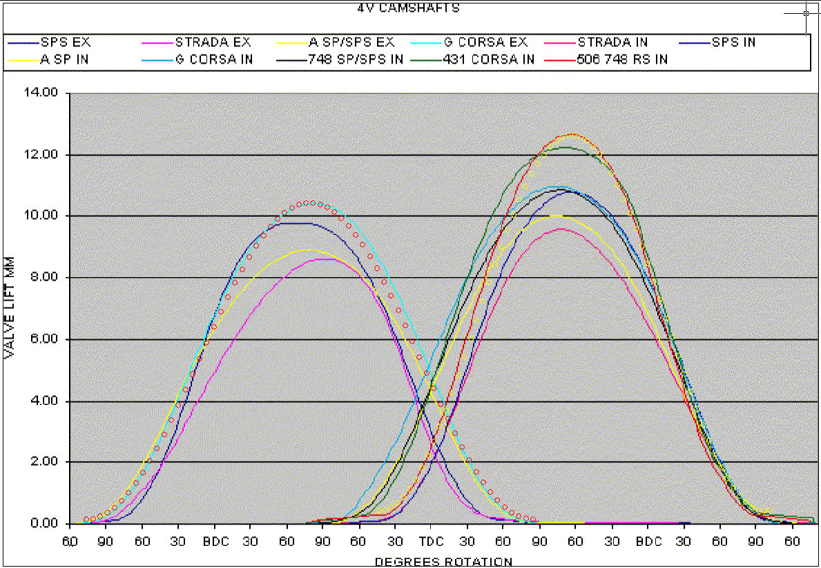
Compare the curve formed by the red circles with the actual cyan curve of the Ducati G-Corsa exhaust valve lift profile.
Then compare the curve formed by the yellow circles with the actual red curve of the Ducati 748 intake valve lift profile.
Your also write:
“For a real cam profile, deceleration is typically under 1/4 of acceleration. This means the spring calculation will be way out. “
Here are the valve lift profiles of the original Honda B16A2 VTEC engine (with the “wild” camlobes engaged, it is a, more or less, racing engine) and of the same engine modified to VVA-roller:
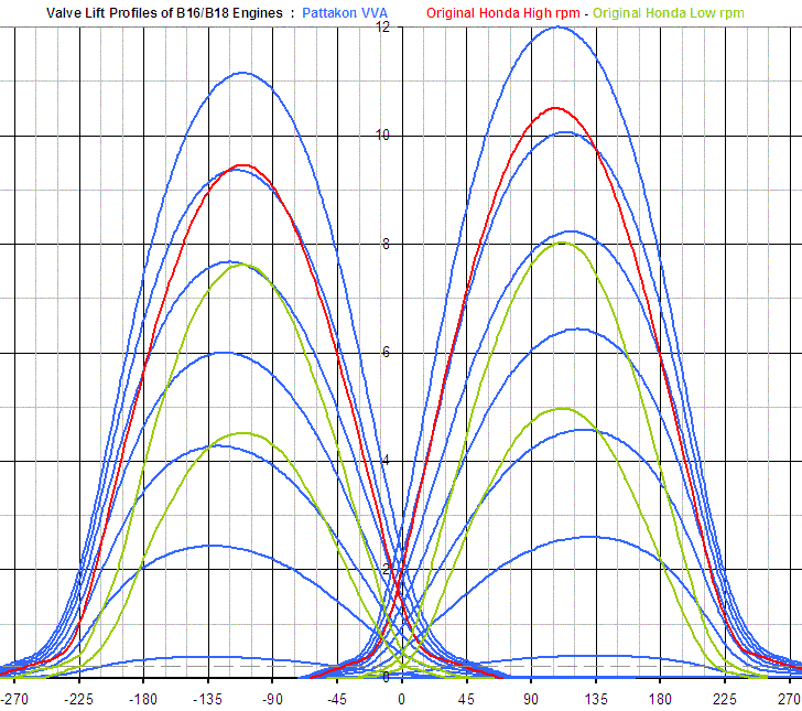
Look at the original (red) curve of the intake valve lift profile. The valve lift is symmetrical about the full open position, which means that the deceleration of the intake valve a little before the full open position (at about 105 degrees after TDC) and the acceleration of the same valve a little after the full open position are about equal. The same is true for the acceleration a little after the valve opening and the deceleration a little before the valve closing (say at 0 and 205 degrees respectively).
For more: http://www.pattakon.com/pattakonVtec.htm and http://www.pattakon.com/pattakonRoller.htm
Youtube video at https://www.youtube.com/watch?v=-zzW8YkReLU
So, are we talking for same thing?
In the high revving engines (see what valve lift profiles the Duactis and the Honda VTEC are using) the shortage of time and the need for the maximum possible valve lift leaves no time to keep the valve fully open for several crank degrees.
You also write:
“The biggest error is assuming that the valve train friction loss is a (guessed) percentage of the k.e. being stored in the spring during each valve opening cycle.”
The calculations are not based on the valve springs.
They are based on the required energy for the opening and closing of the valve.
Either in desmodromic systems (wherein there are not restoring valve springs) or in conventional valve trains.
You also write:
“The biggest error is assuming that the valve train friction loss is a (guessed) percentage of the k.e. being stored in the spring during each valve opening cycle.”
Think simply and you will see how reasonably this assumption is.
You have two parts and a quantity of energy is reciprocating between them.
The taking and giving of a quantity of energy requires forces to act from the one part to the other and vice versa.
The more the required energy and the less the time provided for this taking and giving back of energy, the heavier the resulting forces.
The heavier the forces the higher the friction loss.
Even in the crankshaft – connecting rod – piston mechanism, the friction is a percentage of the inertia loads involved when running without load.
So what is more reasonable than assuming that when a quantity of energy passes from one part of a kinematic mechanism to another, the friction loss is a percentage of the reciprocating energy.
I asked it again in my last post:
Is there a racing engine having 17.7mm valve lift and 120gr “valve mass”, capable for 14,000rpm?
Do you have any diagrams of the valve lift profiles of it?
Do you have a dyno showing the FMEP of such an engine?
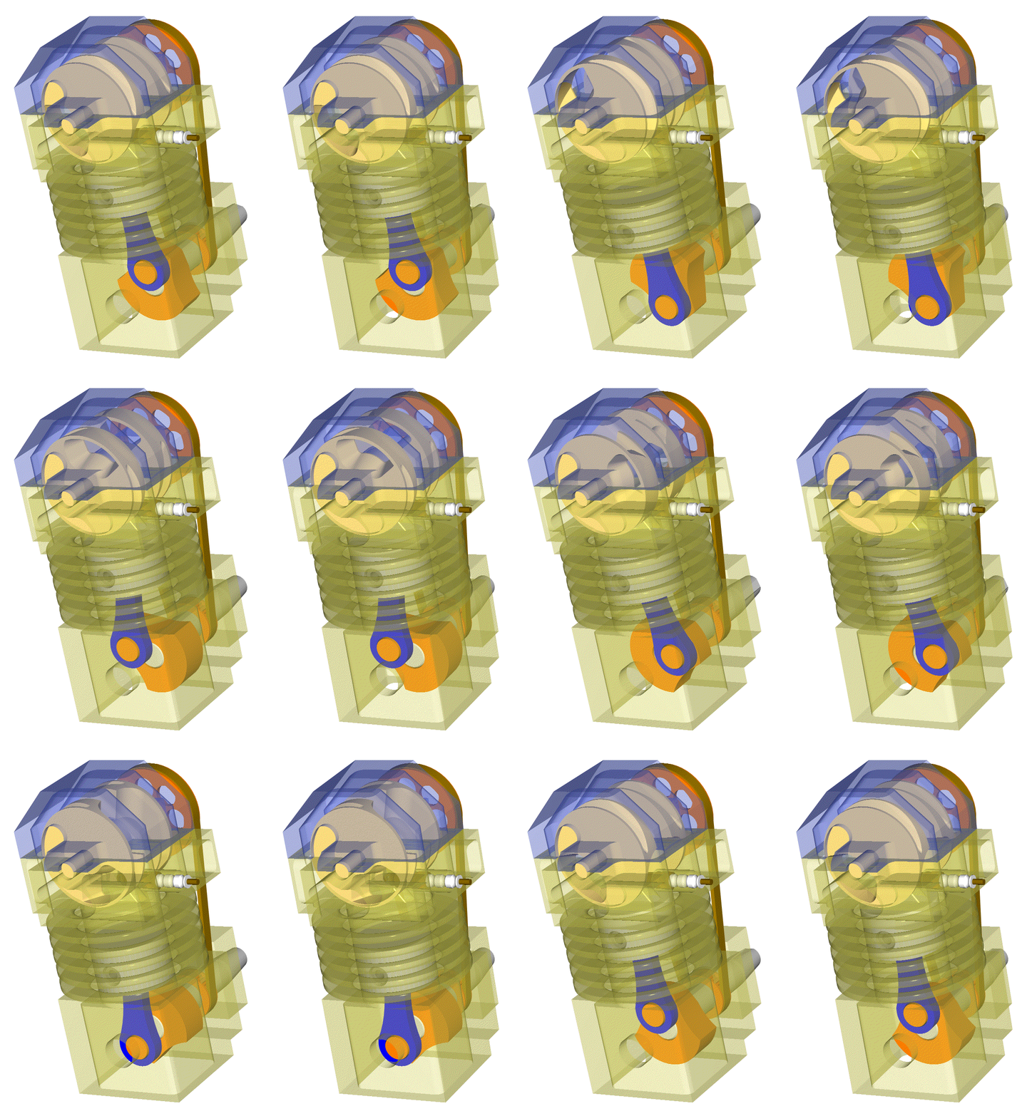
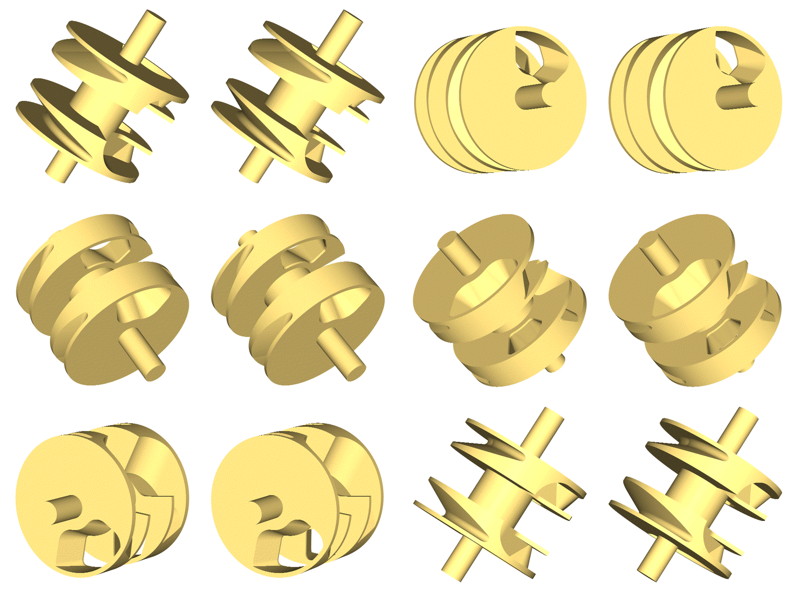
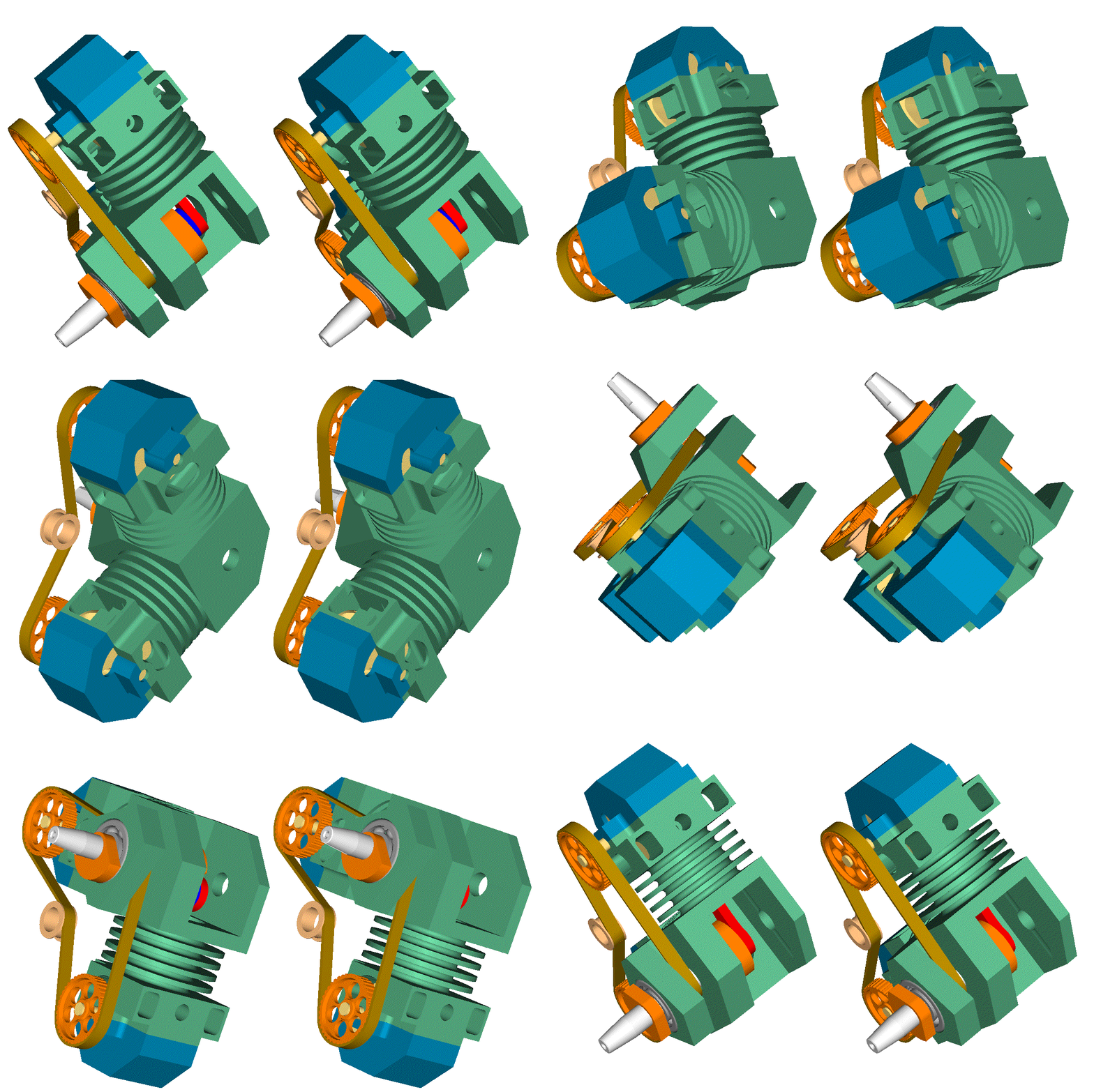
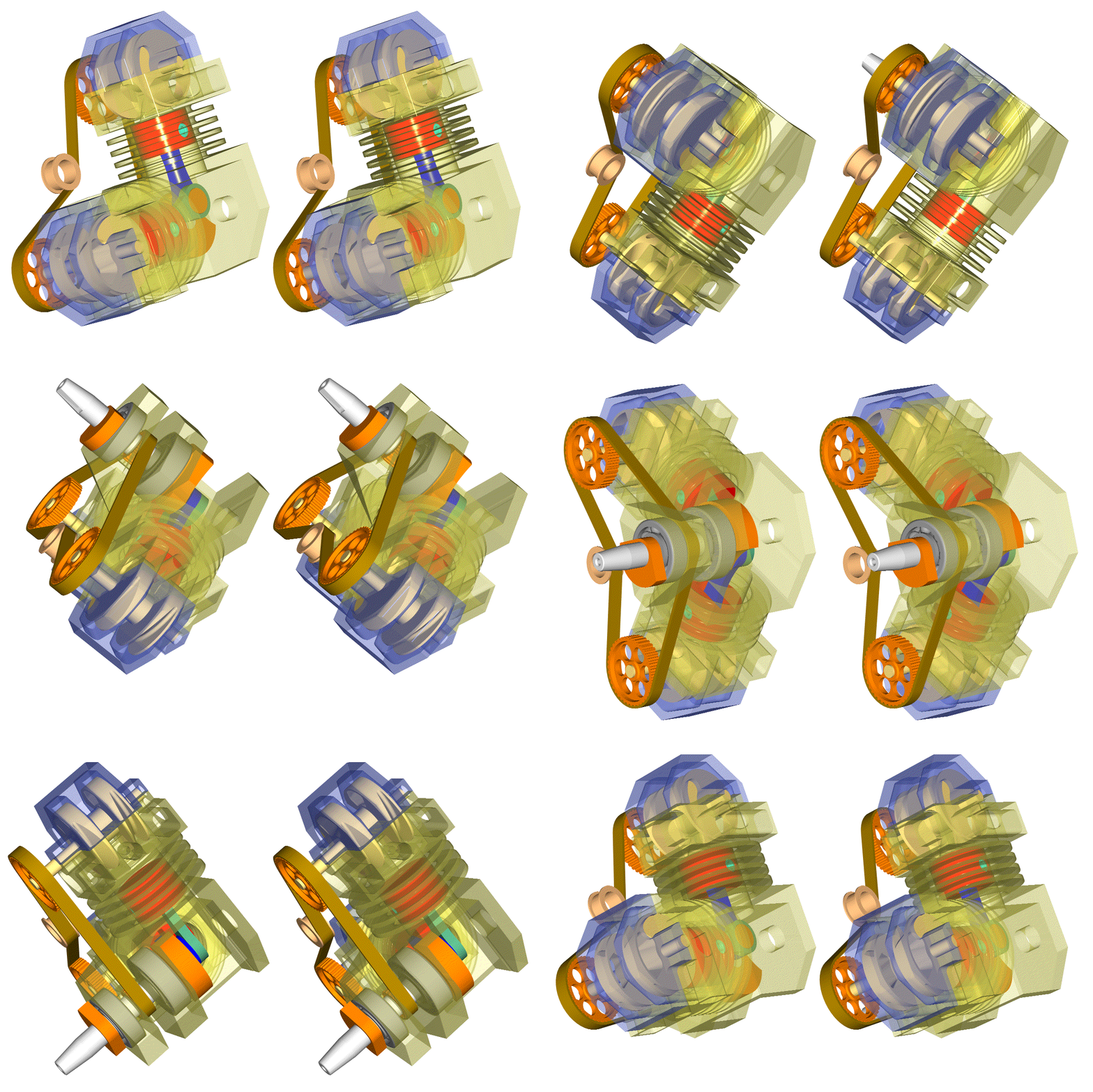
By the way, here is another version of the PatRoVa short stroke model engine:
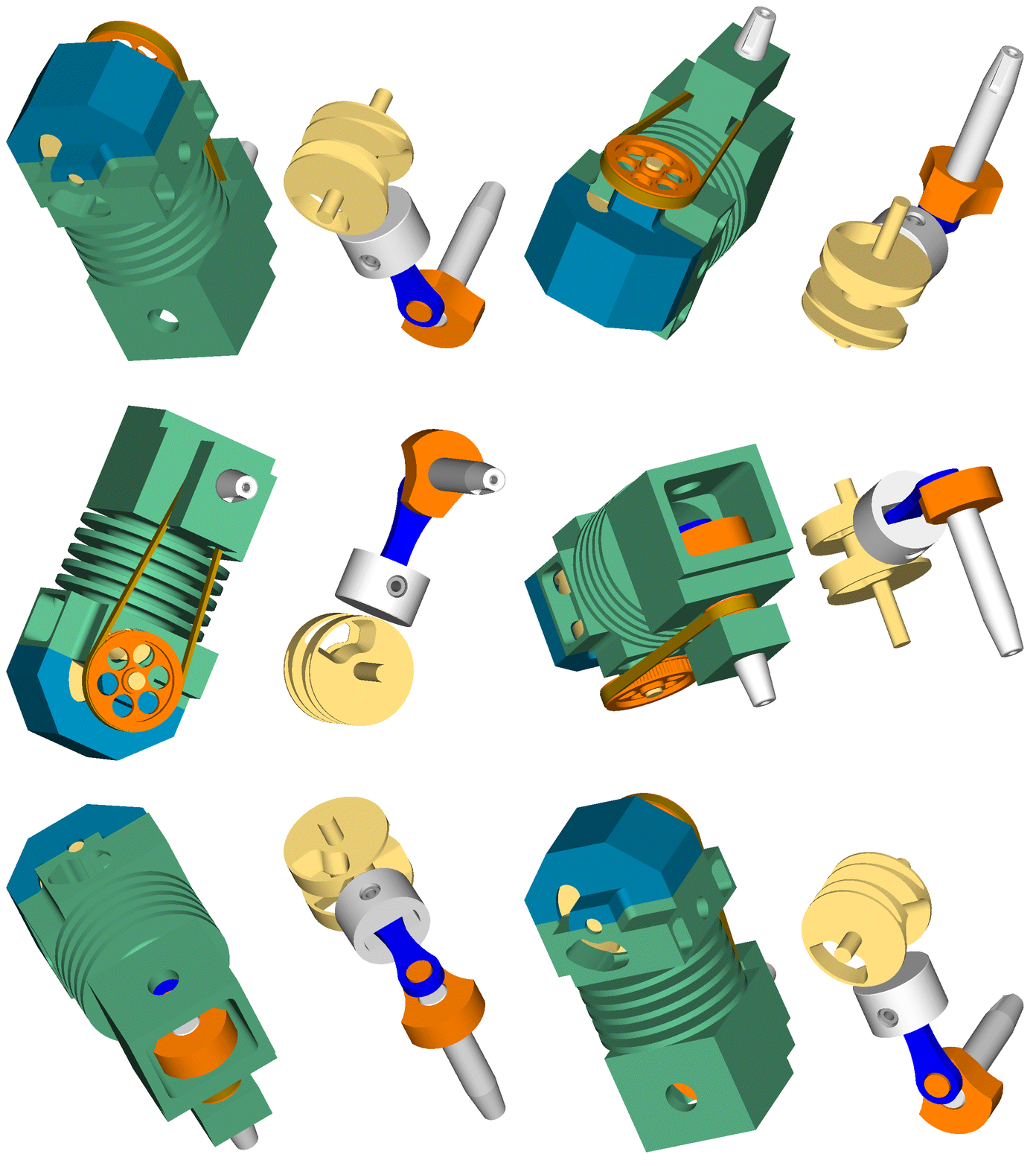
There are two differences as compared to the previous animations.
It has “funnel” exhaust ports (the port area at the outer side of each disk is substantially bigger than at the inner side of the disk).
It exploits the exhaust gas inertia to accelerate a fresh air stream and cool internally by it the exhaust port of the rotary valve as well as the exhaust passageways in the cylinder head.
In the animation the engine is shown at the “overlap”.
The exhaust is near to finish.
The exhaust port in the PatRoVa rotary valve has just started to bridge the exhaust passageways in the cylinder head with a port cut on the head cover (the blue part) providing fresh / ambient air (not air-fuel, just air).
The inertia of the exiting exhaust gas into the exhaust gas piping (not shown) creates a vacuum and suctions fresh air (through the exhaust port of the rotary valve) from the port on the “cylinder head cover”, scavenging the hot gas and cooling internally the exhaust port of the rotary valve, the exhaust passageways in the cylinder head and the rest exhaust piping.
In the specific design, the exhaust port of the rotary valve continues to bridge the “fresh air port” on the head cover with the exhaust for some 120 crank degrees after the overlap.
Note:
In the animation they are not shown the two side covers of the exhaust passageways. Without them, the exhaust gas exits from the sides of the cylinder head. With them, the exhaust gas exits from the two orthogonal holes at the “front” (shown at right) side of the engine (these orthogonal holes are arranged oppositely to the inlet port).
Thoughts?
Objections?
Thanks
Manolis Pattakos

