2014 Design

Here are our CFD links and discussions about aerodynamics, suspension, driver safety and tyres. Please stick to F1 on this forum.
Anon123
Anon123
1
Joined: 16 Feb 2013, 20:33

Re: 2014 Design

Post

n smikle wrote:The 20mm shallower box is going to hurt everybody more than RedBull. Remember how RedBull were running very shallow wings at places that required medium downforce??!
But we've lost the blown diffusers so perhaps they won't have the same advantage.

Lycoming
Lycoming
106
Joined: 25 Aug 2011, 22:58

Re: 2014 Design

Post

They haven't run pillars in the center of any kind for some time now and I don't recall any regulation will force them to, so why would they run swan necks next year? No pillar at all is better than a swan neck pillar.

LMP cars have it because their wings are much wider and the bending moment is so large that supporting it only at the ends is rather impractical. An F1 rear wing is narrower and thicker, so it can support the bending moment created by aerodynamic downforce without center supports.

The only reason I can think of to have pillars is to limit lateral deflection of the wing, but that doesn't seem to be something the teams care about.

CoventryClimax
CoventryClimax
0
Joined: 11 Jan 2014, 17:11

Re: 2014 Design

Post

Lycoming wrote:They haven't run pillars in the center of any kind for some time now and I don't recall any regulation will force them to, so why would they run swan necks next year? No pillar at all is better than a swan neck pillar.

LMP cars have it because their wings are much wider and the bending moment is so large that supporting it only at the ends is rather impractical. An F1 rear wing is narrower and thicker, so it can support the bending moment created by aerodynamic downforce without center supports.

The only reason I can think of to have pillars is to limit lateral deflection of the wing, but that doesn't seem to be something the teams care about.
Im pretty certain he centre beams are back for 2014, thats what most are predicting, and swan necks are certainly the best choice, may be hard to implement due to restrictions...

User avatar
idfx
53
Joined: 20 Dec 2013, 03:18

Re: 2014 Design

Post

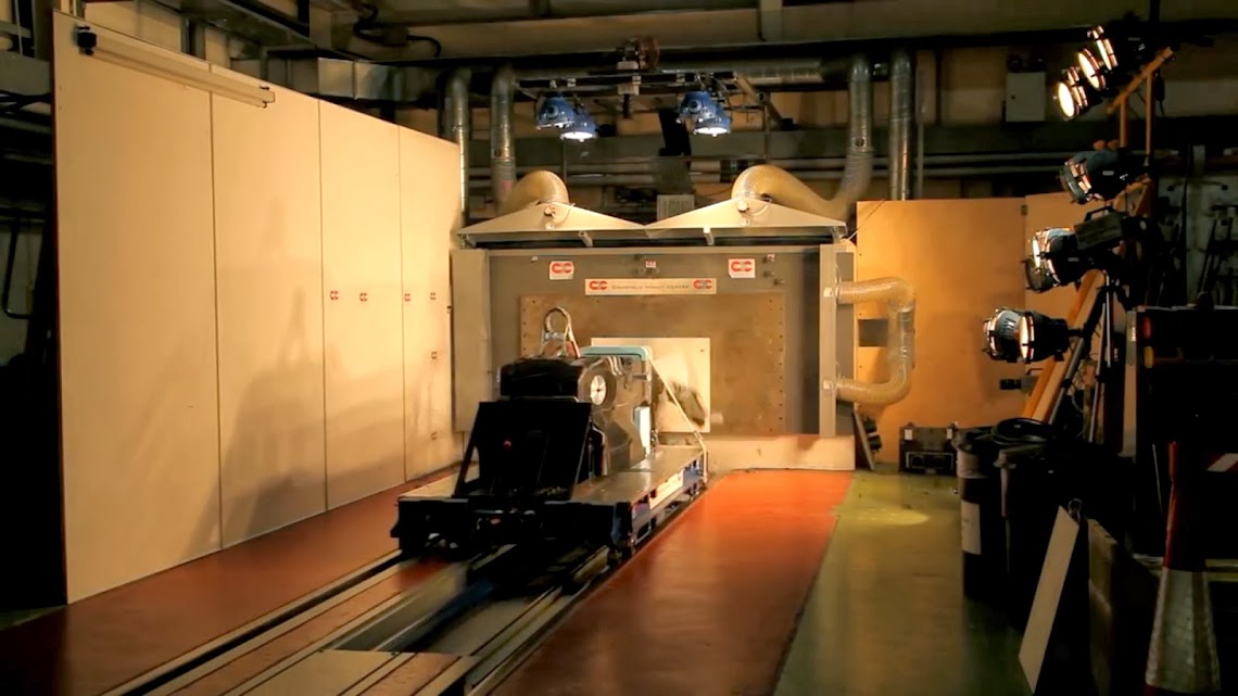
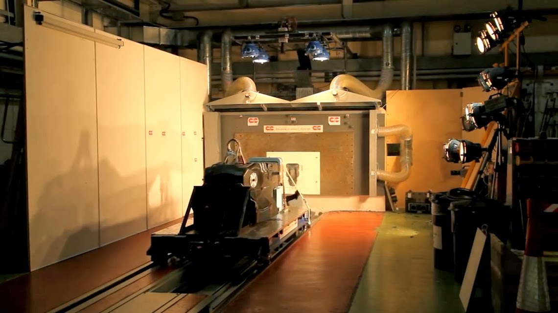
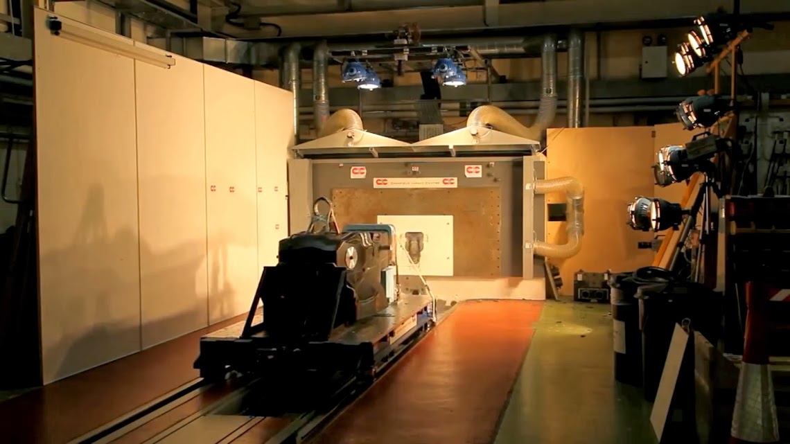
Caterham -> Sequence Screenshot chassis crash test - 2014 - by IDFX :D
Image
Image
Image
Image
Image
Image
Image
Image
Image
Image
Image
Image
Image
Image
Image
Image
Image
Image
Image
Image
Image
Image
Image
Image
Image
Image
Image
Image
Image
Image
Image
Image
Image
Image
Image
Image
Image
Image
Image
Image
Image
Image
Image
Image
Image
Image
Image
Image
Image
Image
Image
Image
Image
Image
Image highres
https://lh4.googleusercontent.com/-5_qS ... st0310.jpg
https://lh6.googleusercontent.com/-di0s ... st0311.jpg
https://lh4.googleusercontent.com/-xi2d ... st0312.jpg
https://lh5.googleusercontent.com/-K8Y5 ... st0313.jpg
https://lh3.googleusercontent.com/-GcyT ... st0314.jpg
https://lh6.googleusercontent.com/-C4q4 ... st0315.jpg
https://lh3.googleusercontent.com/-ntiX ... st0316.jpg
https://lh3.googleusercontent.com/--yz2 ... st0317.jpg
https://lh4.googleusercontent.com/-RAb8 ... st0318.jpg
https://lh6.googleusercontent.com/-b2n3 ... st0319.jpg
https://lh3.googleusercontent.com/-Fh6B ... st0320.jpg
https://lh3.googleusercontent.com/--rqj ... st0321.jpg
https://lh3.googleusercontent.com/-0YXV ... st0323.jpg
https://lh4.googleusercontent.com/-Wzdw ... st0324.jpg
https://lh3.googleusercontent.com/-ZBTb ... st0325.jpg
https://lh3.googleusercontent.com/-WznJ ... st0326.jpg
https://lh6.googleusercontent.com/-P8_S ... st0327.jpg
https://lh3.googleusercontent.com/-GKgY ... st0328.jpg
https://lh4.googleusercontent.com/-lt4D ... st0329.jpg
https://lh5.googleusercontent.com/-6qCl ... st0330.jpg
https://lh6.googleusercontent.com/-OE5Y ... st0331.jpg
https://lh4.googleusercontent.com/-euZv ... st0333.jpg
https://lh4.googleusercontent.com/-clZd ... st0334.jpg
https://lh5.googleusercontent.com/-uOa8 ... st0335.jpg
https://lh3.googleusercontent.com/-LaR4 ... st0336.jpg
https://lh4.googleusercontent.com/-RtIB ... st0337.jpg
https://lh5.googleusercontent.com/-w_gY ... st0338.jpg
https://lh3.googleusercontent.com/-e_oX ... st0339.jpg
https://lh3.googleusercontent.com/-SD3T ... st0340.jpg
https://lh3.googleusercontent.com/-FIJx ... st0341.jpg
https://lh6.googleusercontent.com/-fYgv ... st0342.jpg
https://lh5.googleusercontent.com/-Clpd ... st0343.jpg
https://lh6.googleusercontent.com/-dECk ... st0344.jpg
https://lh3.googleusercontent.com/-vAbp ... st0345.jpg
https://lh3.googleusercontent.com/-_W2G ... st0346.jpg
https://lh5.googleusercontent.com/-N294 ... st0347.jpg
https://lh6.googleusercontent.com/-Ko3F ... st0348.jpg
https://lh5.googleusercontent.com/-ratO ... st0349.jpg
https://lh6.googleusercontent.com/-K_lW ... st0350.jpg
https://lh4.googleusercontent.com/-qY8l ... st0351.jpg
https://lh4.googleusercontent.com/-OZpc ... st0352.jpg
https://lh4.googleusercontent.com/-Oy6n ... st0353.jpg
https://lh3.googleusercontent.com/-Xtol ... st0354.jpg
https://lh3.googleusercontent.com/-X_-r ... st0355.jpg
https://lh5.googleusercontent.com/-sVAr ... st0356.jpg
https://lh3.googleusercontent.com/-6iYM ... st0357.jpg
https://lh5.googleusercontent.com/-uNTl ... st0358.jpg
https://lh4.googleusercontent.com/-UlCk ... st0359.jpg
https://lh4.googleusercontent.com/-eOOg ... st0360.jpg
https://lh4.googleusercontent.com/-C_Aa ... st0361.jpg
https://lh6.googleusercontent.com/-bm0w ... st0362.jpg

Post more tomorrow, the sequence of 0:29. This larger images have more quality
Thanks

edit----
Are two nozzles. The nozzle has a drop down format, is attached directly to the front wing. I believe that Interpretation: A nozzle (top) connected with a front wing with a small rise (drop nozzle) and the columns would be displaced upwards. With that grew louder and the hole also.
Last edited by idfx on 12 Jan 2014, 02:12, edited 2 times in total.
----------

wesley123
wesley123
204
Joined: 23 Feb 2008, 17:55

Re: 2014 Design

Post

Lycoming wrote:They haven't run pillars in the center of any kind for some time now and I don't recall any regulation will force them to, so why would they run swan necks next year? No pillar at all is better than a swan neck pillar.
Previously the load was supported by the beam wing, which is now gone.

They could let the floor carry the load, but then the structure is going to be a big problem. The floor isn't capable of carrying the load, and neither would be the much longer end plates. To get the flexing out is going to require a lot of beefing up on the end plates and floor.
"Bite my shiny metal ass" - Bender

Crucial_Xtreme
Crucial_Xtreme
404
Joined: 16 Oct 2011, 00:13
Location: Charlotte

Re: 2014 Design

Post

Gary Anderson's idea of what some of the 2014 noses may look like.. Which is a bit different to some of the other designs we've seen put forth.

Image
via AutoSport

wuzak
wuzak
467
Joined: 30 Aug 2011, 03:26

Re: 2014 Design

Post

CoventryClimax wrote:
Lycoming wrote:They haven't run pillars in the center of any kind for some time now and I don't recall any regulation will force them to, so why would they run swan necks next year? No pillar at all is better than a swan neck pillar.

LMP cars have it because their wings are much wider and the bending moment is so large that supporting it only at the ends is rather impractical. An F1 rear wing is narrower and thicker, so it can support the bending moment created by aerodynamic downforce without center supports.

The only reason I can think of to have pillars is to limit lateral deflection of the wing, but that doesn't seem to be something the teams care about.
Im pretty certain he centre beams are back for 2014, thats what most are predicting, and swan necks are certainly the best choice, may be hard to implement due to restrictions...
I don't think swan necks can be used as they would be outside the allowed bodywork zones.

wesley123
wesley123
204
Joined: 23 Feb 2008, 17:55

Re: 2014 Design

Post

Then you bring back the wing chord enough to make the swan necks fit.
"Bite my shiny metal ass" - Bender

wuzak
wuzak
467
Joined: 30 Aug 2011, 03:26

Re: 2014 Design

Post

wesley123 wrote:Then you bring back the wing chord enough to make the swan necks fit.
And lose downforce?

User avatar
Holm86
247
Joined: 10 Feb 2010, 03:37
Location: Copenhagen, Denmark

Re: 2014 Design

Post

Wouldn't it be in the 150mm exclusion zone anyways??

Mitsuro Sano
Mitsuro Sano
11
Joined: 13 Dec 2013, 20:59

Re: 2014 Design

Post

ringo wrote:
Mitsuro Sano wrote:
Amazing modeling work!! =D>
That's a good looking car you got there.
Thanks Ringo :)

I've tried another version of the nose with the nose tip still 300mm high.
The first version I've shown earlier had the section defined in the article 15.4.3 using the full width of the nose in order to have the slimmest possible section height-wise and by doing so having the lowest point of the nose as high as possible.
This time, just by curiosity, I've done the opposit, which looks much more like the designs we have seen so far : the section 15.4.3 is now using the full height the rules allows ( the section has to be at least 135mm above the reference plane and at max 250mm ) in order to have the slimmest possible section width-wise ( like the Blanchimont-type nose ).

Here is the global view of that nose :
Image
In comparison with the first version I've done :
Image

In black the nose crash structure, in red, bodywork and in blue where the vanity panel can be:
Image

The strake on the side of the nose is just here for legality reason in order to comply with the rule 3.7.8, because the front of the nose is wider than the back of nose, using the full width available in order to get as much as possible of clean air under the nose.

The nose crash structure alone, with the slot 50mm behind the foremost point of the structure, to make the section 15.4.3 legal:
Image
Image

The underside:
Image

And views from the side and the front :
Image

Image

wesley123
wesley123
204
Joined: 23 Feb 2008, 17:55

Re: 2014 Design

Post

wuzak wrote:
wesley123 wrote:Then you bring back the wing chord enough to make the swan necks fit.
And lose downforce?
You mean, the downforce that is most likely double lost by the pillars having in the way? Seriously, a 3cm loss in chord length over a really small width is hardly missing any profile, and is enough to give room for the swan necks.
"Bite my shiny metal ass" - Bender

wesley123
wesley123
204
Joined: 23 Feb 2008, 17:55

Re: 2014 Design

Post

Holm86 wrote:Wouldn't it be in the 150mm exclusion zone anyways??
Afaik it falls in the same box as the shark fin does
"Bite my shiny metal ass" - Bender

ergenomic
ergenomic
2
Joined: 08 Aug 2010, 08:41

Re: 2014 Design

Post

These vanity panels flying around the place in a collision, at the drivers head level and possible to be thrown into the crowd. These are not tethered and could actually cause a lot of damage or worse. Would hate to see a bad situation arise from badly written rules.

What a stupid solution a vanity panel is!

Manoah2u
Manoah2u
61
Joined: 24 Feb 2013, 14:07

Re: 2014 Design

Post

ergenomic wrote:These vanity panels flying around the place in a collision, at the drivers head level and possible to be thrown into the crowd. These are not tethered and could actually cause a lot of damage or worse. Would hate to see a bad situation arise from badly written rules.

What a stupid solution a vanity panel is!
won't get that extreme, there's no difference there between the possibility between wing parts or normal nose parts that can fly off in a incident. there's been plenty front wings flying everywhere because of contact and nobody got the worse of that.....

vanity panel is a great solution to something ugly and additionally has the possibility to be put purpusefully to use.
"Explain the ending to F1 in football terms"
"Hamilton was beating Verstappen 7-0, then the ref decided F%$& rules, next goal wins
while also sending off 4 Hamilton players to make it more interesting"