Alright you math whizzes..
Is there a way to calculate the burn time at say 10 or 11 thousand rpm?
Statically you about a 1.5 to 1 rod length to stroke ratio but as rpm goes up I'm thinking it's slightly different. 1.7 or 1.3,, which way.
Brian.G wrote:Just to start adding the info before it piles up.
First, the seats
http://i150.photobucket.com/albums/s92/ ... 05aafd.jpg
http://i150.photobucket.com/albums/s92/ ... c5f02f.jpg
An overview,
http://i150.photobucket.com/albums/s92/ ... 11215f.jpg
http://i150.photobucket.com/albums/s92/ ... 57537f.jpg
http://i150.photobucket.com/albums/s92/ ... c05207.jpg
The intake port sides are straight for most of the way. The floor is straight until indicated below with the blade in the SSR shot,
http://i150.photobucket.com/albums/s92/ ... 0f2995.jpg
Close-ups of the various details - use ruler for sizing - It will give the opportunity to take real dimensions from any location without having to list,
http://i150.photobucket.com/albums/s92/ ... bcdacd.jpg
http://i150.photobucket.com/albums/s92/ ... 568843.jpg
http://i150.photobucket.com/albums/s92/ ... 38f63a.jpg
http://i150.photobucket.com/albums/s92/ ... ca03b7.jpg
http://i150.photobucket.com/albums/s92/ ... 4aad09.jpg
http://i150.photobucket.com/albums/s92/ ... 2f7907.jpg
http://i150.photobucket.com/albums/s92/ ... 8ba301.jpg
Lots more to add yet including cross-sections, volume, angles and valve sizes but its on the way.
Ive made up my mind also to perform some other flow tests as well as flowbench tests using either particle image velocimetry, or ink trace - In both cases a clear casting is made of the port/chamber and you can then view the flow/turbulence within it.
Ill get the hard measures mentioned above out of the way first. These should give good insight - the rest Ill share in 3d form once I get the silicone scanned.
More very soon,
Brian,
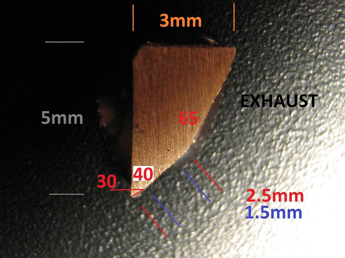
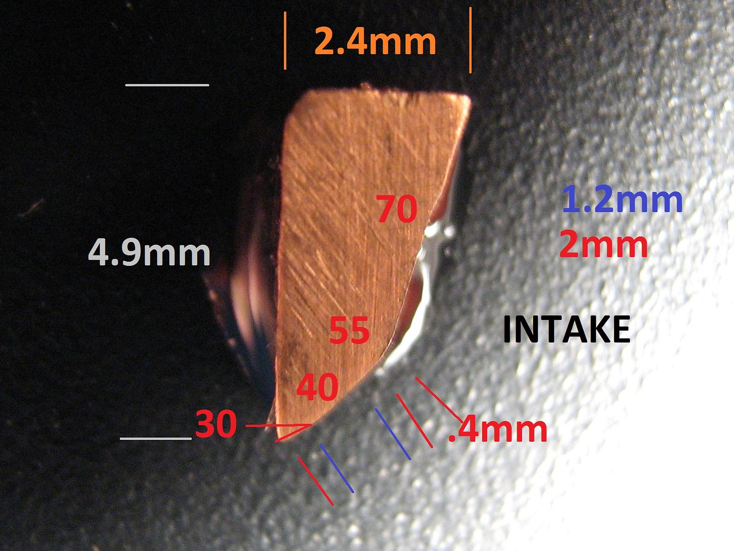
The "seats" are the 40 degree section in each photo. The seat width is indicated by the pair of blue dimensioning lines and the number in blue i.e. 1.5mm exhaust and 1.2mm intake.hondaballs wrote:It seems to me it's 55 and 65 from this pictureBrian.G wrote: First, the seats
http://i150.photobucket.com/albums/s92/ ... 05aafd.jpg
http://i150.photobucket.com/albums/s92/ ... c5f02f.jpg
Geoff,GeoffH wrote:Hi Brian.
Nice to see you are still around and that you have posted more information.
I am actually thinking of undertaking a similar project if I can get hold of a suitable donor cylinder head.
I take it you didn't just take a hacksaw to the cylinder head? I assume you used a powered saw of some type with the head held rigidly. After cutting did you do any other surface treatment like milling?
Keep up the good work, I look forward to see your future information, especially the 3D data.
Geoff
not reallyriff_raff wrote:Looks like the seats are BeCu. It's amazing that they got those thin section seats to stay put in the cylinder head, especially the 2.4mm wall seats used on the intake side. With such a thin radial wall section the amount of interference fit you can use when installing the seats is limited. Too much interference and the thin section seat will yield.
Thanks for taking the time to sign up and type the above - you are welcome.IVX8 wrote:Excellent engineering analysis. I am struck by the high quality of the castings, at least compared to the ones I receive from my foundry. I very much appreciate the work on the oil system, this is such a major part of the thremal management. I learned a lot. Thanks you.