[KVRC ~ish] CCE LMP01

Post here information about your own engineering projects, including but not limited to building your own car or designing a virtual car through CAD.
User avatar
machin
162
Joined: 25 Nov 2008, 14:45

Re: [KVRC ~ish] CCE LMP01

Post

Ric, that is bloody brilliant!

I'm out at the moment but will take a look properly later!
COMPETITION CAR ENGINEERING -Home of VIRTUAL STOPWATCH

wesley123
wesley123
204
Joined: 23 Feb 2008, 17:55

Re: [KVRC ~ish] CCE LMP01

Post

Impressive improvement!

I'm interested in what the cause is for the (relatively) large amount of the drag at the very rear?
"Bite my shiny metal ass" - Bender

User avatar
RicME85
52
Joined: 09 Feb 2012, 13:11
Location: Derby

Re: [KVRC ~ish] CCE LMP01

Post

Could it be the shape of the rear wheel cover/fender? I have a version with a flat top from the rear wheel centreline to the very rear ready to try.

User avatar
machin
162
Joined: 25 Nov 2008, 14:45

Re: [KVRC ~ish] CCE LMP01

Post

wesley123 wrote:Impressive improvement!

I'm interested in what the cause is for the (relatively) large amount of the drag at the very rear?
RicME85 wrote:Could it be the shape of the rear wheel cover/fender? I have a version with a flat top from the rear wheel centreline to the very rear ready to try.
There is definitely some lift and drag caused by the curved rear face of the wheel fairing (note blue area)... But that is just behind the rear wheel centre line... And the drag profile shows that the peak you're talking about is being generated right at the back of the car... At that point I think the wheel fairing is flat anyway (?) so any positive pressure on that face will act downwards and any negative pressure will act directly upwards. I.e. Not drag.. So it is either simply down to the upper rear wing element, or maybe the vertical rear face of the back of the car.... Maybe you could do a surface pressure plot looking at the back of the car?

One thing is for certain: you shouldn't need to do big changes now: the main elements of the car seem to be working OK, so now it really is a refinement job, and you should be really strict with doing one change at a time IMO.

There is still a fair amount of circulation in front of the side pod which is annoying.... And that low pressure over the top of the leading edge area of the front suspension fairings is also annoying, but I suspect it'll be hard to rectify that without a big drag increase (on the positive side; that low pressure around the front of the suspension fairing is producing thrust as well, so it is actually decreasing your drag a little!).

So I agree the rear wheel fairing is one thing that could be improved... But I suspect (as Variante has suggested too) that the diffuser is still the area to concentrate on, but now with the knowledge you have a good starting basis to fall back on if you hit a dead end.

Could you do a horizontal velocity slice at a height of about 100mm above the ground? I.e. So we can see the velocity distribution through the diffuser? As I say, at the weekend I was playing around with a car model and found huge gains (DF increase and Drag decrease) just by trying to manipulate the flow into and through the diffuser...
COMPETITION CAR ENGINEERING -Home of VIRTUAL STOPWATCH

User avatar
RicME85
52
Joined: 09 Feb 2012, 13:11
Location: Derby

Re: [KVRC ~ish] CCE LMP01

Post

At that point I think the wheel fairing is flat anyway (?)
Nope, it is curved.
Image

Not sure how to do velocity and surface pressure plot (unless the velocity is the slices I have been doing but obviously on a horizontal axis)

User avatar
RicME85
52
Joined: 09 Feb 2012, 13:11
Location: Derby

Re: [KVRC ~ish] CCE LMP01

Post

I assume its to do with the drop down box on the toolbar?
I have these:
Image

User avatar
machin
162
Joined: 25 Nov 2008, 14:45

Re: [KVRC ~ish] CCE LMP01

Post

Yep, for a velocity slice It should just be a case of including the "internal mesh" in the analysis, and then selecting "U" (the one with the cube next to it) on the list of parameters in the drop down box at the top of the screen whilst the slice is selected.... I suspect my version of paraview is a few iterations old so things might have moved on....

The surface pressure plot is just like the ones you've been doing already... In fact if you take that last picture you showed of the wheel fairing and zoomed out a bit so we can see the whole of the back of the car that would be good...
COMPETITION CAR ENGINEERING -Home of VIRTUAL STOPWATCH


User avatar
CAEdevice
49
Joined: 09 Jan 2014, 15:33
Location: Erba, Italy

Re: [KVRC ~ish] CCE LMP01

Post

I'm trying to use surfaceLIC but I can't find the right command (after loading the pluging)... but, first of all, what exactly does SurfaceLIC show?

User avatar
RicME85
52
Joined: 09 Feb 2012, 13:11
Location: Derby

Re: [KVRC ~ish] CCE LMP01

Post

I had issues with SurfaceLIC not showing in one of the versions of Paraview. Which version are you using?
4.3.1 64bit is working fine for me
Image

User avatar
machin
162
Joined: 25 Nov 2008, 14:45

Re: [KVRC ~ish] CCE LMP01

Post

So, in what I guess is probably going to be the final step of our little collaboration I thought I would do a final analysis of the CFD. (Again, this is presented for Newbies and not directly at you guys!)

The two main areas as discussed before I think are the diffuser and the flow in the middle of the car.

The flow in the diffuser area is showing the effects of the entrainment of the rear wheel contact patch wake (I've exaggerated the blue area on the velocity plot for clarity, see below). This low velocity "cloud" spreads out and starts to "take over" the diffuser. I've found that adding diffuser strakes can help to control the spread of that low velocity "cloud" and increase downforce and decrease drag... so this might be something to have a play with amongst others.

In front of the side-pod side there is still that area of recirculation. Maybe you should try your/Wesley's idea to extend the front suspension fairing to enclose the side-impact structure to further prevent this air moving vertically and direct it through this area and out of the sides of the car instead, and I think you can improve the leading edge of the floor as well: remember air doesn't like flowing across a "sharp" object: it just detaches...

Image


Once you've had a play with those (and other aspects of the diffuser, such as different expansion ratios, different angles, etc) then you're down to looking at small areas of the body to look for improvements. As we said before: you're looking for low pressure areas on top and back of the body which manifest themselves as areas of lift and drag.

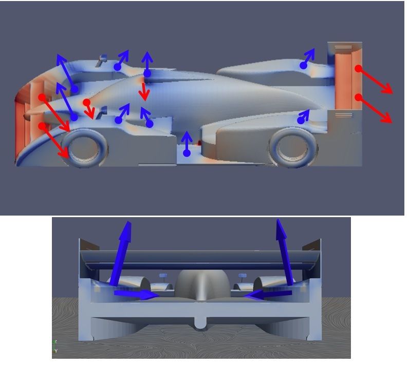
On the images below I've marked on the direction of the resultant forces due to the surface pressures (These are just perpendicular to the surface): anything pointing vaguely backwards is creating drag and upwards is causing lift. I don't think there is a huge amount to be gained here, but maybe a few modifications to the tops of the wheel fairings could be tried; remember you're trying to avoid downward curving surfaces... sometime purposely causing the air to separate from the bodywork can be of benefit (i.e. so the air doesn't follow the downward curving bodywork and create lift).
Image

You may also want to try changing things like slot gaps and wing element profiles, although yours seem to be working quite well...

Also remember that any gains in Downforce at one end need to be balanced with more downforce at the other end...

And finally: best try one thing at a time so you can be sure how each change has affected the car...

I'm sure we all look forward to following your car development further so keep us posted on your thread!
COMPETITION CAR ENGINEERING -Home of VIRTUAL STOPWATCH

User avatar
RicME85
52
Joined: 09 Feb 2012, 13:11
Location: Derby

Re: [KVRC ~ish] CCE LMP01

Post

Excellent conclusion to the experiment there Machin =D>

I have run a couple of tests today and thought you might be interested in the results.

Test 1
Changed the rear section of the rear wheel pod so that it has a flat top. To do this the rear wing elements have been raised and the slots in the endplates have been removed. (these changes are in the following tests too)

Image

Image

Image

Image

Image

Image

Test 2
Changed the front suspension cover to resemble the rear suspension cover on Variante's early car.

Image

Image

Image

Image

Test 3
Changed the front suspension cover to resemble the front suspension cover on Variante's early car.

Image

Image

Image

User avatar
machin
162
Joined: 25 Nov 2008, 14:45

Re: [KVRC ~ish] CCE LMP01

Post

That is cool.. not a huge improvement then, but a little (note COP has moved backwards slightly though).

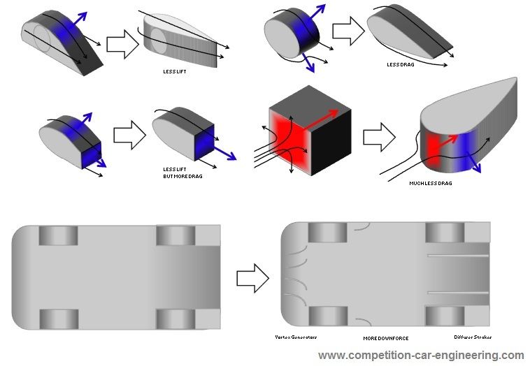
Actually I thought I'd do another post(!)... this one is kind of a "If this....then try this...". The idea being that someone can identify areas of undesirable pressure on the surface of their car, find on the drawing below the applicable/nearest shape and then try out the proposed shapes to try and get rid of the undesirable pressure...

...Then underneath those I've put in a few ideas for manipulating flow in the underfloor and diffuser which I found to have a big improvement on drag and downforce... The curved objects in my case were 25mm tall "fences" which generated vortices... The ones at the floor edge behind the front wheels were used to attempt to seal the floor from the high pressure air outside the car. The diffuser strakes seemed to help control the rear wheel wake where it spilled into the diffuser (as mentioned in my last post), and to be honest I'm not entirely sure what the vortex generators under the leading edge of the floor actually did -I put them in to see if they would affect the rear wheel wake in the diffuser, but I do know they increased downforce and reduced drag!

(You probably can't apply these vortex generator ideas directly because of the flat floor rule, but maybe you can try to generate the vortices either in front of the leading edge of the floor, or down the sides of the car near the floor?)

Image

EDIT: I reckon you should have a play with the diffuser next....!
COMPETITION CAR ENGINEERING -Home of VIRTUAL STOPWATCH

User avatar
machin
162
Joined: 25 Nov 2008, 14:45

Re: [KVRC ~ish] CCE LMP01

Post

Looking again... Test 1 came with a significant increase in drag... So some part or all of that change should be taken off the car... I wonder if it is the lack of wing end plate slots that is doing the damage?
COMPETITION CAR ENGINEERING -Home of VIRTUAL STOPWATCH

User avatar
machin
162
Joined: 25 Nov 2008, 14:45

Re: [KVRC ~ish] CCE LMP01

Post

Or the inside face of the new wheel fairings? Those dark blue patches under the wing do face backwards slightly...

Image

On the previous picture of the rear there looked to be significantly less dark blue on these panels (and the panels were not as tall because of the drop down behind the wheel): looks like it is better to accept a little lift over the wheel in favour of less drag...
COMPETITION CAR ENGINEERING -Home of VIRTUAL STOPWATCH