Suspension uprights?

Here are our CFD links and discussions about aerodynamics, suspension, driver safety and tyres. Please stick to F1 on this forum.
dp35
dp35
0
Joined: 15 Nov 2006, 00:58

Re: Suspension uprights?

Post

Did some more searching on the web, found this nice photo and description of a Honda F1 upright:
Image

This website also has other nice photos of the Honda F1 car.
http://www.scotts-se7en.co.uk/hondaf1_orange.htm

User avatar
flynfrog
Moderator
Joined: 23 Mar 2006, 22:31

Re: Suspension uprights?

Post

Do you happen to have a V8 atom by chance

dp35
dp35
0
Joined: 15 Nov 2006, 00:58

Re: Suspension uprights?

Post

flynfrog wrote:Do you happen to have a V8 atom by chance
Nope, mine's just a lowly 245hp Honda 4 banger. The V8 Atom is owned by "the other dp". Hopefully he'll have the bugs worked out of that one soon.

User avatar
flynfrog
Moderator
Joined: 23 Mar 2006, 22:31

Re: Suspension uprights?

Post

dp35 wrote:
flynfrog wrote:Do you happen to have a V8 atom by chance
Nope, mine's just a lowly 245hp Honda 4 banger. The V8 Atom is owned by "the other dp". Hopefully he'll have the bugs worked out of that one soon.
I have been following the other one :mrgreen:

pitlaneimmigrant
pitlaneimmigrant
0
Joined: 29 Jun 2008, 19:42

Re: Suspension uprights?

Post

Back to topic, I understand that uprights are typically machined from Titanium. While metal matrix composite (MMC) materials are allowed, the maximum stiffness of metallic materials is limited which might restrict the MMCs you could use

User avatar
PlatinumZealot
559
Joined: 12 Jun 2008, 03:45

Re: Suspension uprights?

Post

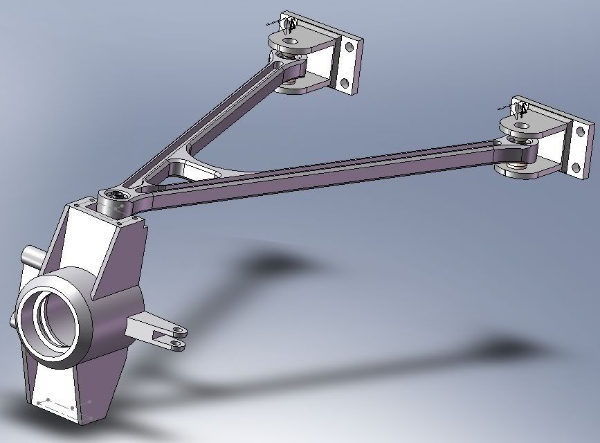
I have to revive this topic.. I am designing a Tube frame race car just a small idle project. I am doing the suspension uprights now and I want to know what axis is best to orient the control arm bearings that connect to the upright?

I notice some people orient the bearing mounts along a Vertical axis... (which i think is better in terms of bearing loading)

Some people orient them in a horizontal axis. (I think this one is more compact).

This is my incomplete upright and control arm, aluminum. The bearings are oriented vertically. Thing is I think I want to make it simple and light.. I think I have to make it simpler and lighter??? ..

...I don't know..

what would you guys change about it?

Image
🖐️✌️☝️👀👌✍️🐎🏆🙏

Racing Green in 2028

dedge
dedge
0
Joined: 28 Jan 2007, 20:42
Location: France, Toulousô

Re: Suspension uprights?

Post

Hello n smikle! Please do not forget to post as many pictures as you can, as I am probably not the only fan of that kind of thing!

For your arm, I would say that you can improve it a lot!
First of all, I would have used some extruded profiles, welded together with CNC extremities. The gain will be a better aero efficiency, and for sure better stiffness. You can keep your V shape, but add the small stiffener closer to the body fittings.

If, for aesthetic reasons, you want to keep it CNC machined, than it is different. To my mind, the "H" profile is not well oriented. I think the more stress will from an horizontal bending, so if you use a "H" profile, the center web will not be stressed that much, but the side flange will be. And you will have something we call "unfolding" effect (I am not sure of the english word, this is the word we use in aeronautics). So a "I" profile will be better to my opinion.

For the bearing orientation it is simple : you have to check the maximum angle of rotation the ball can admit. I can check but it will be probably around 7-10°. If you think you will have more than that, than tilt your bearings. But you design is the best for me, as the stress effort is better distributed along the suspension movement.

Jersey Tom
Jersey Tom
166
Joined: 29 May 2006, 20:49
Location: Huntersville, NC

Re: Suspension uprights?

Post

I'd start by making the control arm from welded steel tube rather than billet aluminum.

As for the spherical bearings.. either orientation works. What's more important IMO is to make sure the friction level is as low as possible.

I assume that upright will be welded steel? In which case it looks like it will be fairly heavy.. particularly the bearing housing. Depending on your cooling requirements you may need to figure a way to pass air through the upright around the bearing carrier and to the rotor.

Hard to totally see below, but you get the idea.

http://4.bp.blogspot.com/_PvE8SOLu3Gc/S ... rassy1.jpg
Image

http://4.bp.blogspot.com/_PvE8SOLu3Gc/S ... ucting.jpg
Image
Grip is a four letter word. All opinions are my own and not those of current or previous employers.

User avatar
flynfrog
Moderator
Joined: 23 Mar 2006, 22:31

Re: Suspension uprights?

Post

I would put the Spherical bearing in double sheer

User avatar
mep
29
Joined: 11 Oct 2003, 15:48
Location: Germany

Re: Suspension uprights?

Post

So first of all you don't need the H-profile on the a-arms because they don't see any bending moments.
You can make them very simple by using a laser cutted and welded steel plate or
some steel tubes.
It will make them lighter compared to stiffness, aero efficient and cheap to manufacture.

For the orientation of the bearings:

Both ways work, but there are advantages and disadvantages.
You must think about how to mount the a-arm.
You will have to move it on one plane in it's final position.
For this all the bearings should be orientated around the same axis.

The vertical one seems to be better for this.
Especially when you think of some manufacturing tolerances you will have.
So the ends of the V might not totally fit into the suspension pick up points.
For this you will have to push the ends a bit.
It is easy when they bearings are orientated around the vertical axis and when the
ends are open like you have it now.

When your bearings are orientated around the horizontal axis then your a-arms
might get twisted in some way when you try to get them into the pickup points.

Disadvantage of the vertical arrangement is the limited rotation angle of your bearings.
The max. angle is somewhere around 8°.
So for ensuring enough wheel travel you will need to orientate your pick up points to the a-arm.
This will make the design and the manufacture a bit more complicated.

spacepig
spacepig
0
Joined: 14 May 2009, 22:48

Re: Suspension uprights?

Post

mep wrote:So first of all you don't need the H-profile on the a-arms because they don't see any bending moments.
You can make them very simple by using a laser cutted and welded steel plate or
some steel tubes.
It will make them lighter compared to stiffness, aero efficient and cheap to manufacture.
They may not see bending loads, but they certainly do see compression. A flat plate will buckle at a very low compression load, so having some section is very important. It doesn't matter whether it's an "H" or an "I", and the way you've drawn it is far easier to make.

Switching to a vertical bearing orientation is really only necessary if you need more angularity. Don't forget to steer it in the model at the bump and rebound travel limit.

marcush.
marcush.
159
Joined: 09 Mar 2004, 16:55

Re: Suspension uprights?

Post

I would rethink the dimensioning very thoroughly ..why you use very bulky wishbone pickup points to the chassis,why do your a arms have parallel constant crossection?
as it is all machined anyways using CNC you have the choice of puting material where you need it.
to my mind the sphericals should be pressed in and staked ,you will save a lot of unneeded thickness in that area and less parts wich can fail.This will help to get the whole assy sleaker and maybe you can quench a little more angular movement out.
The horizontal orientation of the sphericals is limiting the suspension travel (droop?)severely .Not an issue with f1 but maybe on your application.
where is the adjustment for camber ,caster and toe? You need to think about adjustment ,also quick service,what about Ackerman ,Bumpsteer? Having the fixed steering arm you are nailed in that position.Additonally in case you have the slightest wack to the steering the whole EXPENSIVE Upright has to go into the bin...no good idea.
Also atthe end of the angular movement of the sphericals contact to machined edges, possibility to squeeze fingers ,think about the poor devil (you?) who will
be bitching about in the paddock in the middle of the night..

I would personally fabricate the wishbones and CNC the uprights..or better cast them

User avatar
mep
29
Joined: 11 Oct 2003, 15:48
Location: Germany

Re: Suspension uprights?

Post

spacepig wrote:
They may not see bending loads, but they certainly do see compression. A flat plate will buckle at a very low compression load, so having some section is very important. It doesn't matter whether it's an "H" or an "I", and the way you've drawn it is far easier to make.
Look at this:
Image

The tube will not buckle that easy.
This solution is much better than the one milled from alu.

spacepig
spacepig
0
Joined: 14 May 2009, 22:48

Re: Suspension uprights?

Post

mep wrote: The tube will not buckle that easy.
This solution is much better than the one milled from alu.
I didn't say a tube would buckle, I was responding to the suggestion to make wishbones from flat plate(!). Fabricated wishbones are pretty obvious, but there's actually a lot to be said for machining them from billet. Production car wishbones tend to be forged or cast with an H beam section very similar to what the OP drew.

User avatar
PlatinumZealot
559
Joined: 12 Jun 2008, 03:45

Re: Suspension uprights?

Post

Thanks for the responses, seems I should have added more information.


Before I explain. all the final dimension are to be put in last, right now I was trying to get familiar with the basic design.

Here goes (Sorry I am too lazy to quote one by one).

This is the rear upright, it is aluminum, it weighs about 3.6 lbs. The back is machined out (pictures coming up). I agree it can be lighter, you guys really have me thinking about it more now. The arm is aluminum too, ~1.6 pounds. It is 0.5m long in the picture but it will be much smaller when I finalize it.

Mounts
The mounts are to have shims behind them for adjusting the arm. I changed the pictured design to somethings simpler, pics coming up.

Beam
Correct, there is no bending moments transferred to the chassis through the arms because of the bearings. But the arm does experience internal bending moments in each member because the two arms are joined(fixed) at the end where they meet. It is like a sideways cantilever taking horizontal loads. Each bearing provides a moment not to itself but to the opposite beam.
There is compression yes. Yes, The orientation of the "I" is not ideal since the load is sideways not up and down. Thankfully the stress in the web was still low. In terms of bucking the arm stood up to 4500N (1000lbs) it would buckle at 7200N (1600lbs) so it is strong in buckling (and stronger when i make it to the shorter final size).
I can turn it into an "H" but the main reason I chose the "I" is because ease of machining. with the H it would be hard to machine the inner sides of the "V"

Aerodynamic profiles.. I like the idea, these arms are under Fenders though. But I guess a square extruded profile is also a good idea. Steel arms.. I have a steel CA model, 3/4 inch tubing it is much stronger but heavier as expected. I think 2.8 or 3 lbs. I have not tested for deflection yet so maybe the steel design can win out.


Bearings and end
The ends of the arms are thick for real. I didn't really know how much I can cut them down, because I wasn't completely sure of how the bearings are fastened.
I think the bearings are to be pressed in for sure, but when you say staked? (marcush) do you mean a Grub screw, circlips or some bonding glue?

The bearings are in double shear, the drawing is just incomplete. There are some caps that are bolted on over the arms. I think I might get rid of the caps and change the whole upright to one piece now though.

The bearing clearances are OK.. getting some good angles out of them. So it seems the vertical bearing axis is good to go then.

Again thanks for the response.
I will post updated pictures later. I considered all of the suggestions and I definitely have more questions coming up.
🖐️✌️☝️👀👌✍️🐎🏆🙏

Racing Green in 2028