Machin, my guess is that there's still a transverse pressure gradient at the end of the strake, and the triangular shape is studied to take advantage of that. Basically, that's a secondary vortex generator.
I'm using a similar feature in my car: if you look closely at my diffuser's strake, you'll notice a first and wider stage ending quite early, and a second, smaller one going on up the trailing edge of the diffuser. The first stage takes care of the larger and more powerful vortices that are shed from the leading edge of the diffuser; the problem with those vortices is that they don't follow very well the curvature of the diffuser itself (as well as loosing energy quickly). That's why the second stage exists, shedding much smaller, yet quite effective, vortices.
Now, a further step would be putting all of this together to form a system of vortices. That's why for the third race of the championship I've tried to make all those vortices interact constructively. It looked like a success in my private tests, but it revealed to be failure when the official results came out. Nowadays, until I'll have CFD settings sorted out, I'm using the less elegant version, the one with non interacting vortices.
BTW I could reveal some more details about how vortices used to interact under my old diffuser, if someone is interested.
As promised, some more words (and images) about vortex management under my cars' diffusers.
First of all, a comparison between an F1 diffuser without strakes...
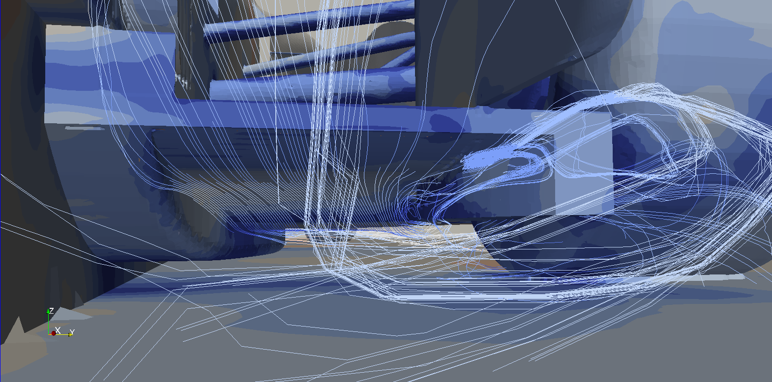
...and the same F1 diffuser with strakes:
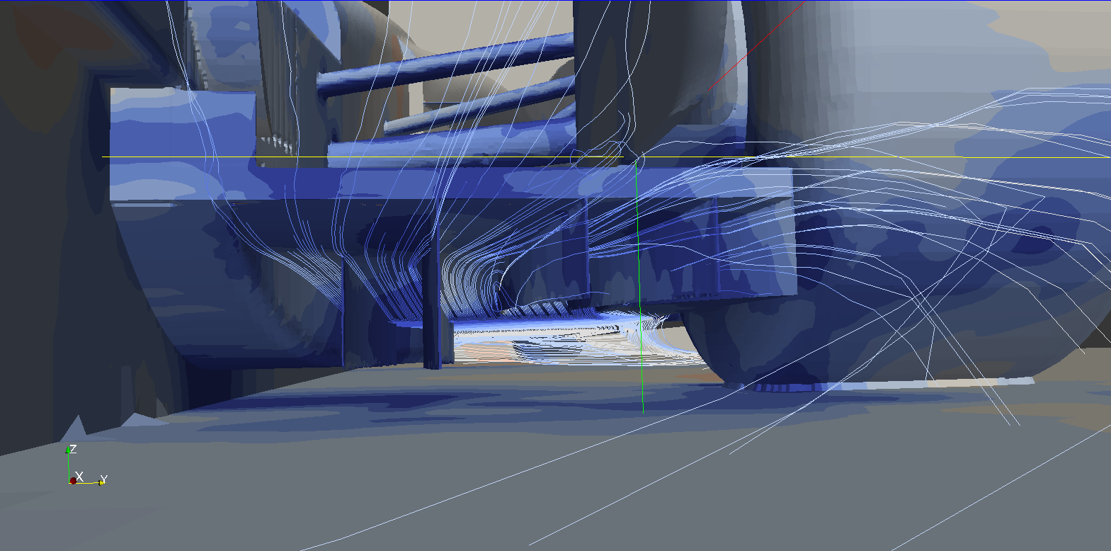
as you can see, in this case strakes prevent stall and allow for greater sideways expansion.
Now the same comparison with the wingless car that i've used for the Magny-Cours low drag race:
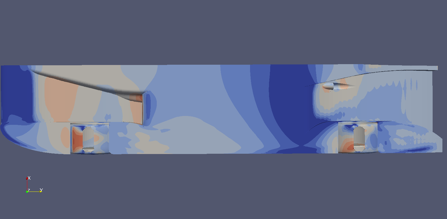
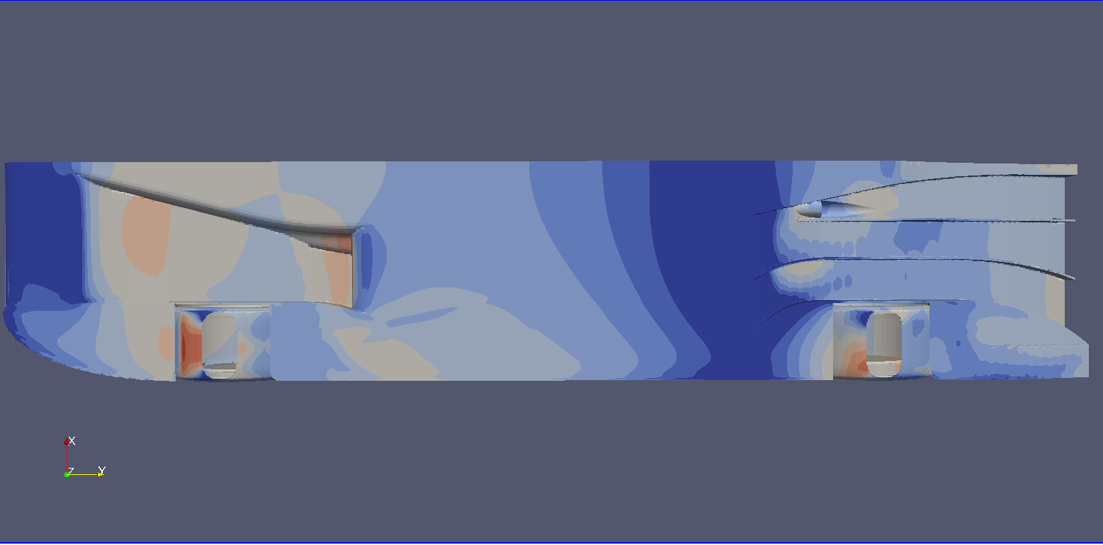
the net downforce gain was 250N (KVRC testing conditions).
Now, the first version of the car featured this configuration:

in this case the strakes do NOT participate actively to vortex generation. On the contrary, they are designed to avoid contact with the primary vortex in order not to disrupt it.
The reason why those strakes are there is to control the flow on the final part of the diffuser, where flow energy is lowest and separation risk is greatest; they simply channel the incoming airflow down the trailing edge in the most “ordered” way, distributing expansion among the whole width of the diffuser.
Further developments brought me to a different approach: a solution featuring full lenght and vortex generating strakes. Here you can see an early version of it:
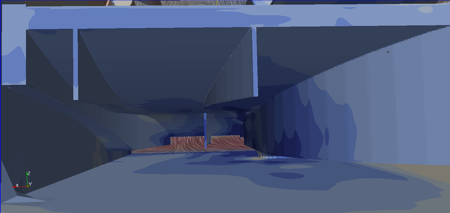
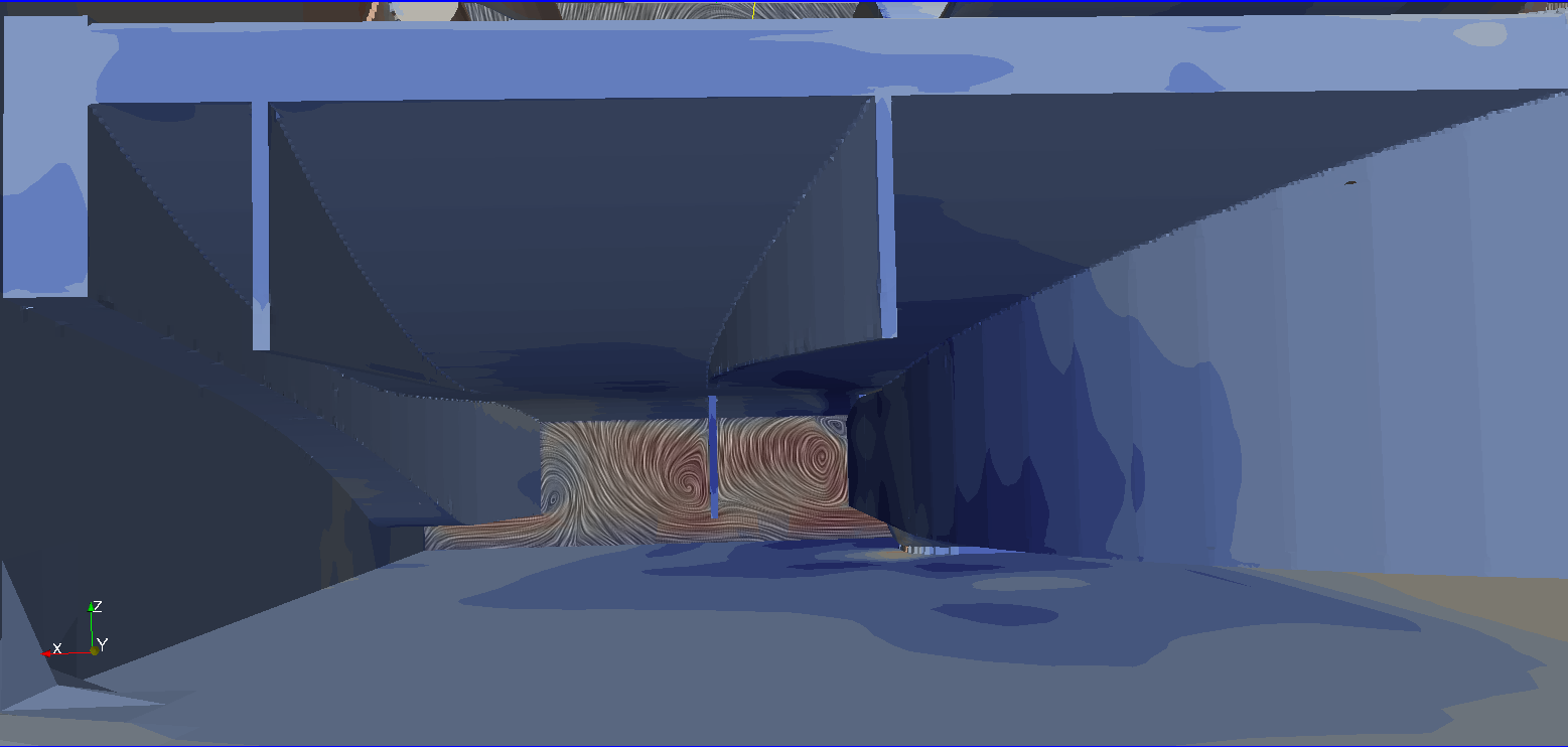
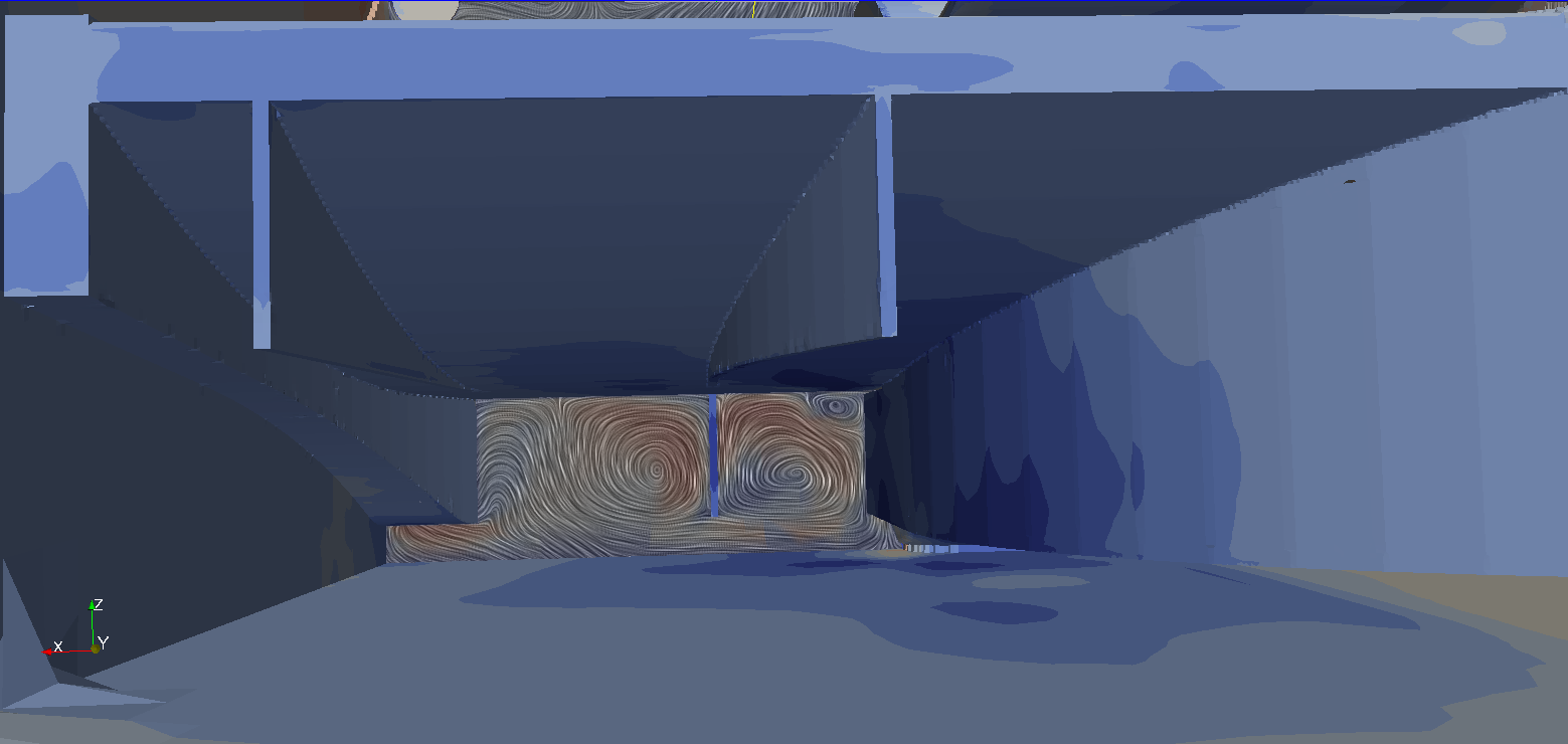
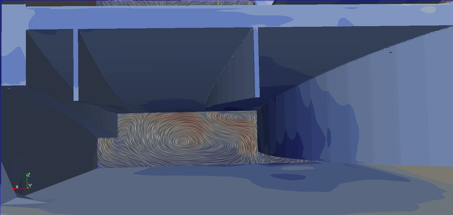
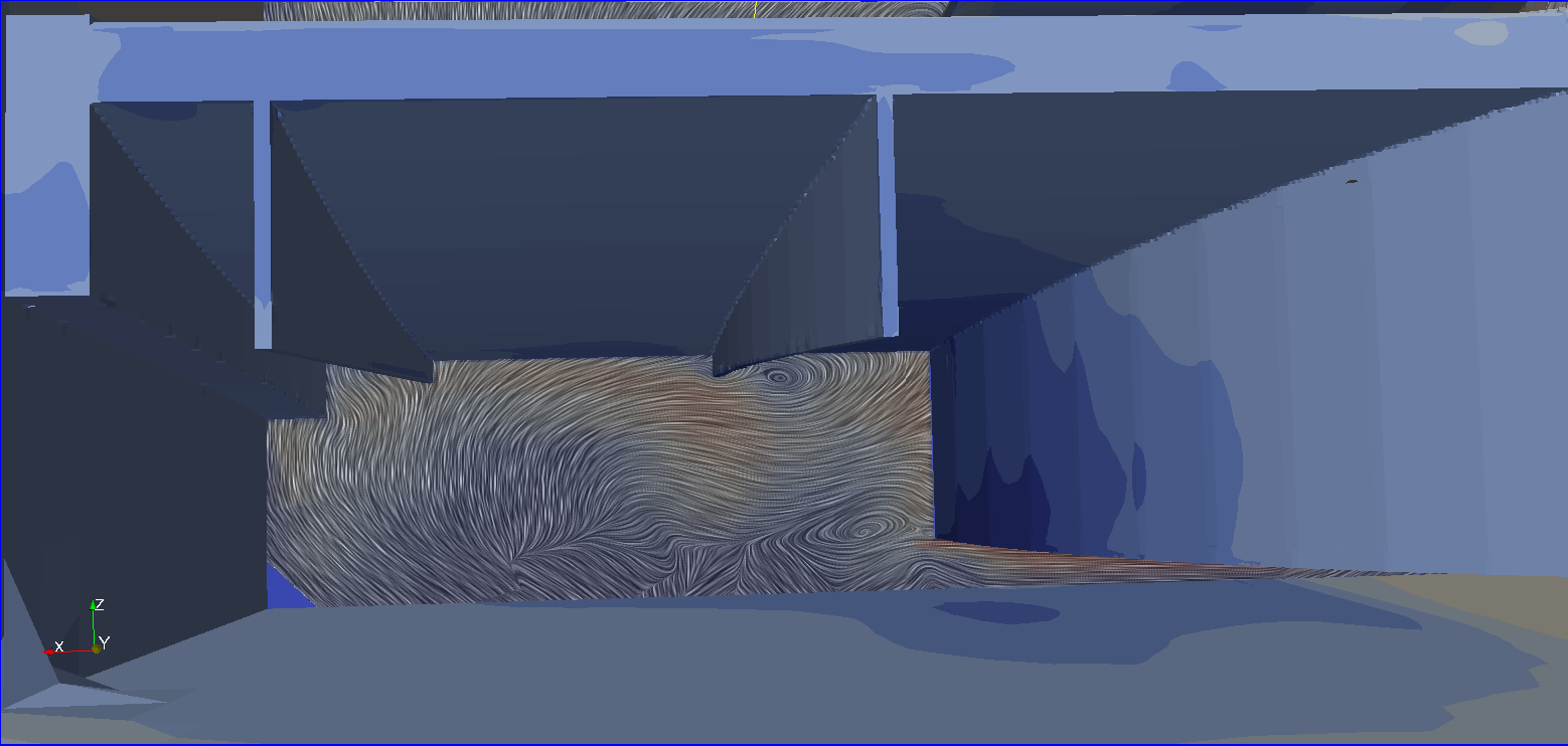
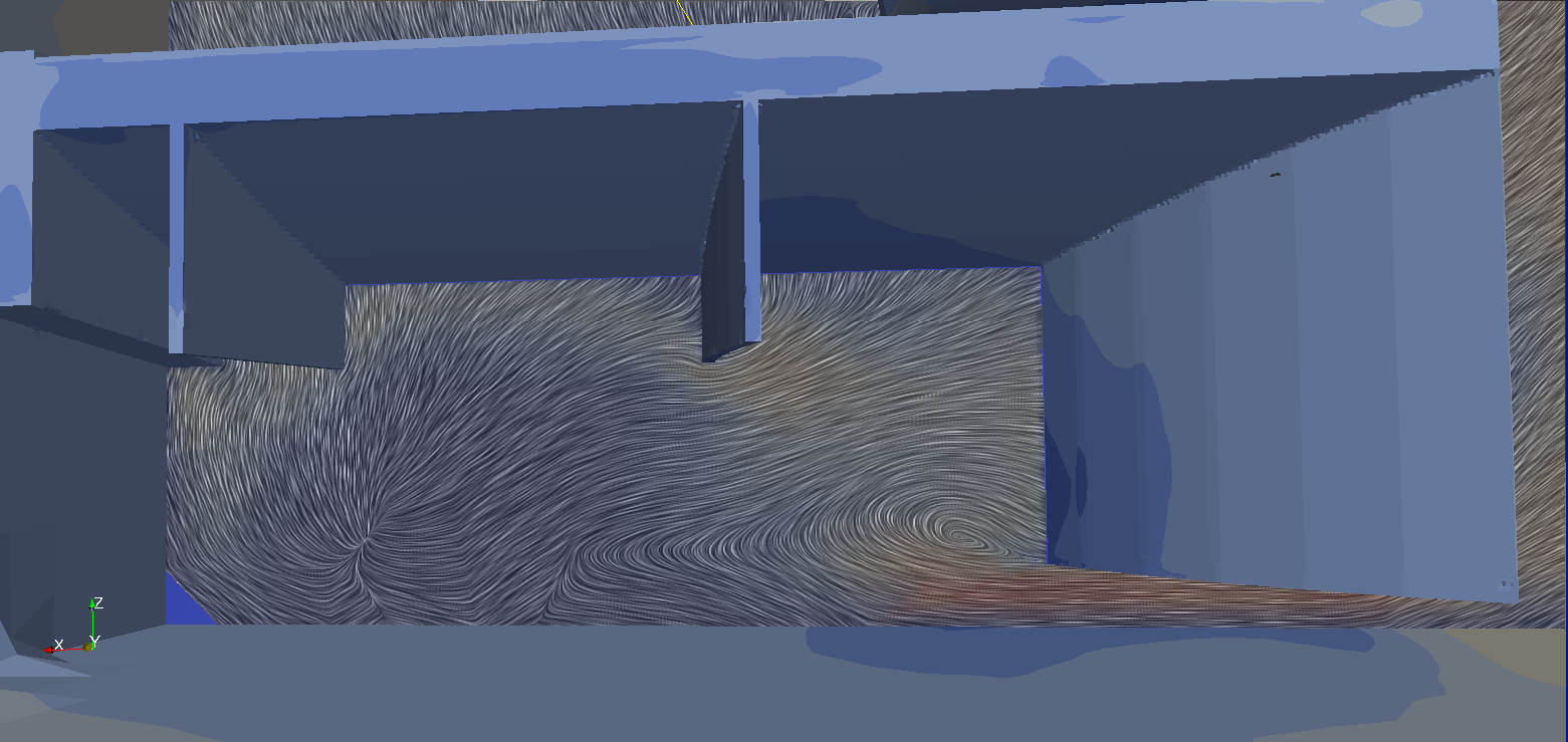
compared to the older version, the new strakes start from the diffuser's throath, generating two primary vortices (instead of a bigger one). This configuration brings the low pressure peak more inwards, exerting more suction under the floor rather than on free stream...
Since this geometry isn't optimized, we can see secondary vorticous formations (luckily stable ones) along the primary vortices.
As we approach the second stage of the diffuser, the vortices start loosing energy rapidly, bursting moments later (in another configuration it looked like even more stable vortices couldn't follow the curvature of the diffuser properly). New vortices are required. Because of the primary vortices, the airflow now goes outwards: a new strake takes advantage of this aspect creating a smaller vortex (counter-rotating compared to the previous ones).
The possibilitied offered by such configuration are huge: we could make the primary vortices merge to avoid bursting, create smaller vortices that follow the curvature of the diffuser, use the pressure differential behind the rear tyres,...
I actually tried some of these solutions, with good results (at least with my solver settings...), but i cannot show them yet, for obvious reasons...
Thoughts? Questions?


