Open Source Racecar

Post here information about your own engineering projects, including but not limited to building your own car or designing a virtual car through CAD.
User avatar
Tim.Wright
330
Joined: 13 Feb 2009, 06:29

Re: Open Source Racecar

Post

Caito wrote:How you came to the suspension pickup points? I'm guessing you have no tire data.
If you don't know push/pullrod or direct connection, how can you design the chassis if you don't know where is that force going?
My thinking is pretty much what Greg and Tom are saying. Basically, your can get (for arguments sake) 80% of what you want without knowing the detailed behaviour of the tyres. This 80% being a suspension which is not doing anything stupid kinematically, will give predictable performance in terms bump/roll steer, camber etc and a load transfer distribution which is related to the mass distribution (like the tyre size) which will not be picking up a wheel at 0.3G or something similarly stupid.

The last 20% will come from a deeper understanding of the vehicle and tyres. This means building some adjustability into the design which of course adds weight, complexity etc but there is no other way if you don't have force/moment data.

On the spring actuation, regardles of all the hype here about push rod/pull rod, there is no tangible difference between the two from a suspension point of view. At least not at the conceptual level (the current pull-rod circle jerk in F1 at the moment is all based on aerodynamic advantages). Therefore, at this early stage I'm more interested in what the wheel rate is going to be but I know I can achieve it with push/pull rod or maybe even direct acting suspension. When you are designing the kinematics, the spring only gets in the way. Getting the motion ratio to behave well using the kinematics is iterative and time conusming, so you don't want to go through that every time you change your A-arm geometry. Therefore I'm leaving that puzzle, and the decision of spring actuation until after I have the A-arm geometry OK.

Regarding the packaging, there is a very simple geometry which represents the maximum packaging space of a tyre which is published as a standard of sorts by the ETRTO. If you put this in your CAD model, you will be pretty sure you won't have packaging problems.

Tim
Not the engineer at Force India

Greg Locock
Greg Locock
235
Joined: 30 Jun 2012, 00:48

Re: Open Source Racecar

Post

marcush. wrote:wasn´t your point the other day that any ... adjustability is a weakness of the whole design ?
That may have been what you read, it wasn't what I wrote. The easy way to adjust bump steer and ackerman without moving the outer tie rod is to move the rack. That's eliminated one high stress bolted joint from the spindle. Other ways would be eccentric taper plugs for the outer tie rod, and so on.

User avatar
Tim.Wright
330
Joined: 13 Feb 2009, 06:29

Re: Open Source Racecar

Post

I needed to do some CAD work to see this moving on a bit.

I've been concentrating on the front axle geometry to get myself to a starting point. I've been jumping between catia and adams for the last week and I'm now at what I'd call base 1. That is a suspension design which could theoretically be packaged and built. I need to do the same to the rear as well then I will start to iteratively improve them using a mix of adams suspension and full vehicle analyses.

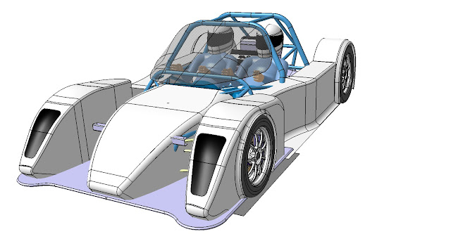
Of course I wasted some time with the bodywork too. Sometimes my brain is not in the mood for numbers, but the results here I'd say are a slight improvement over the last body model.

Image

Image

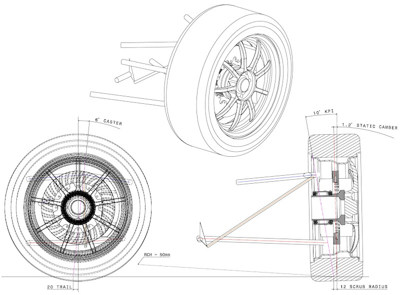
So here is my front axle basic geometry. The procedure to get to this stage was:
1. Choose tyres
2. Choose wheels (at the moment OZ Alleggerita 16" front/17" rear)
3. Set kingpin geometry (KPI and Caster)
4. Brake system (AP racing have drawings of all their stuff so that helped a lot so...
CP3580-2636/2637 front disc and CP5040 front caliper)
5. Upper and lower ball joint
6. The roll centre height and anti dive requirements then decide the locations of the wishbone members.

Image

First question for anyone knowlegable: What are your opinions on the steering geometry in terms of caster, KPI, trail and scrub? Im planning on using a non assisted rack to cut down on mass and complexity. But I don't have any feel at the moment if the design will be too heavy to drive. This will be one of the main thing I want to see in the full vehicle simulation. At the moment the specs on the steering (open to comment!) are;
Caster = 6deg
Caster trail = 20mm
KPI = 10deg
Scrub radius = 11mm
Steering ratio = 14.8 (+/-360deg)
Rack speed = 52.3mm/rev
Steering limits = +/-31deg on the ground for +/-450deg swa
Ackermann = 15% from memory and can't increase atm due to the brake disc

This brings me to question 2: Can anyone recommend a good source for lightweight manual steering racks in Europe? So far I've found Titan and Jack Knight in the UK. They can do custom racks, but I'm also open to using something from an OEM application which is in the range of 500-800mm long and with a ratio of between say 40-60mm/rev.

Regarding the roll centre height and anti dive, I have set them at 50mm and about 40% respectively. They are just baseline values for now and I will refine them more once I have a full vehice model to work with. My intention is to do a little investigation on roll centre heights using a simplified model in to see the effects they have on the frequency response of the car. This will be a bit time consuming but also will be very intersting. I'Ve never become too involved in the public circle jerk over roll centres because I've never actually done the experiment with them. Though I think I've got a reasonable idea on what they are and what they are not.

If I get some time later this week I will post up the kinematic and steering curves for discussion (if anyone are interested).

Next steps for me are to start work on the rear axle though this depends a lot on the engine/gearbox. I think I need to go buy these soon :wink:

Here are my current hardpoints. All correct except for the tie rod which is now;
Outer = 110, 763, 314
Inner = 150, 365, 296

btw, origin is at the front axle on the ground. X is positive forward, Y is positive left and Z is positive up.
Image
Not the engineer at Force India

Jersey Tom
Jersey Tom
166
Joined: 29 May 2006, 20:49
Location: Huntersville, NC

Re: Open Source Racecar

Post

Tim.Wright wrote:I've been jumping between catia and adams for the last week
Nice toys to have :)
Grip is a four letter word. All opinions are my own and not those of current or previous employers.

Tommy Cookers
Tommy Cookers
642
Joined: 17 Feb 2012, 16:55

Re: Open Source Racecar

Post

@TW
the trail seems too small to me
the steering axis offset seems about right
how about 7-8 deg castor angle (or at least provision for easy change of angle) ?

BTW it has been said that a good spaceframe does not benefit from use of high strength tubing eg expensive 4130
(customer Lotus race cars were made from very cheap ERW (a rolled and welded) grade)
you show bends that would be formable only with fully softened material ?
Last edited by Tommy Cookers on 19 Feb 2013, 23:28, edited 1 time in total.

Jersey Tom
Jersey Tom
166
Joined: 29 May 2006, 20:49
Location: Huntersville, NC

Re: Open Source Racecar

Post

Tommy Cookers wrote:TW it has been said that a good spaceframe does not benefit from use of high strength tubing eg (expensive) 4130
In theory, yes. In practice, I've found you can get such a wider array of 4130 tube OD & wall.. and it welds so nice.
Grip is a four letter word. All opinions are my own and not those of current or previous employers.

silente
silente
6
Joined: 27 Nov 2010, 15:04

Re: Open Source Racecar

Post

Nice project.

i am with tommy cookers about caster. Although the caster trail gets not too big, i would start with something more than 6 degrees and maybe use it also to have some camber gain when steering, taking some camber gain out from the arms geometry, so that you can start with less static camber and also have less camber change in braking, thus having more rubber on the ground for the front wheels (and, in theory, more grip potential).

About steering racks, many CN prototypes cars manufacturer have used in the past some racks coming from FIAT cars. Above all some old ones were particularly favourable about steering ration and dimensions, but i don´t remeber the numbers right now.

Out of my curiosity, where are you going to build this car? Are you doing it yourself?

Jersey Tom
Jersey Tom
166
Joined: 29 May 2006, 20:49
Location: Huntersville, NC

Re: Open Source Racecar

Post

I don't see the fundamental need for more caster and/or trail.
Grip is a four letter word. All opinions are my own and not those of current or previous employers.

User avatar
Tim.Wright
330
Joined: 13 Feb 2009, 06:29

Re: Open Source Racecar

Post

Thanks for the comments guys.

I will take the comments regarding the caster on board. I hadn't thought of the camber change while braking. I will add this to my list of things to investigate once I have the full vehicle model running. Ideally I would setup a range of simulations with different caster and camber gains and see if I can pick a good direction to go. One problem here is that a lot of tyres are parameterised without any camber sensitivity to braking forces. So I need to think how to decide how much camber under braking is too much.

About the comment on the trail, I have delibrately made it all quite small because I don't want to use a power assisted rack and I don't want a huge steering ratio. So my only option to keep the steering effort down was to reduce the trail and scrub. What would be the main reasons to increase it? I think driver feedback is the only function of trail and scrub.

Regarding the chassis frame, I haven't yet decided on a material or thought too deeply about manufacturing just yet. I think a lot of this will be determined after some discussions with Tuev here in Germany. I would like to get it licensed for the road so soon I will start takling with them about what my options are for getting it approved. I'm suspecting it will be quite difficult though.

Ideally I'd like to use 4130 soley because it will perform better in a crash. But I agree in normal operation there is no gain in stiffness to be had. Will likely come down to cost... if I have to pay a coded welder to do the frame, I think 4130 would be quite a stretch pricewise. I didn't understand the point on the bends requiring a soft material. Is there a minimum radius for moly type steels? I do recall cracking some 4131 sheet while bending up rockers at uni. I need to make myself aware of the limitations there because I intend to do the uprights out of fabricated 4130 sheet steel.

Cheers guys

Tim
Not the engineer at Force India

Greg Locock
Greg Locock
235
Joined: 30 Jun 2012, 00:48

Re: Open Source Racecar

Post

"But I don't have any feel at the moment if the design will be too heavy to drive. This will be one of the main thing I want to see in the full vehicle simulation. "

You don't actually need a full vehicle sim for that. You can do that with pen and paper starting from a plot of Fy and Mz vs Ay for the front tire, and how much the KPI is and so on. That'll give you a plot of SWT vs Ay. Admittedly if you are building an ADAMS model then you get that calc for free. There's two philosophies there, some people don't build an ADAMS model until they have the design more or less sorted on paper, others use CAD and ADAMS in tandem to actually develop the whole concept from scratch. At work that's what I do, it is slightly more expensive in terms of my time, but by the time we are thinking about physical prototypes it means the ADAMS model is in a very good state, it probably save 2 months in the most time critical part of the program.

So far as castor goes, less is more. Corvette runs 3.5 degrees, lots of cars 4-6 degrees. if you think you need more than 7 then you must have a good reason.

Also remember to separate out castor trail from castor.

silente
silente
6
Joined: 27 Nov 2010, 15:04

Re: Open Source Racecar

Post

Sorry, i was not clear in my post.

I didn´t mean you have to increase caster trail. I was actually say to keep it low, so to be careful with it. Normally, if you don´t take care about it, when you increase caster you also increase longitudinal trail, which could be not ideal if you want to run the car for "normal customers" without power steering. But there are easy ways to increase one without increasing too much the other.

My concept about caster is that, when you steer, it produces more negative camber on the outside wheel and that could be a nice way to have the camber "you like" on the more loaded wheel without having to set more negative camber in static conditions or without the need of more camber gain, which would lead to more negative camber also in braking situations, when the car dives and the front suspension goes in a jounce movement.

Now, how much is ideal? difficult to say, it of course depends also on the tyres. I know pacejka models doesn´t pick camber influence on longitudinal forces in braking conditions. I did some studys on that when i was doing FSAE and my uni joind the Tire Test Consortium and i had access to rough data. But each tire is somehow different than the others.

In general i can tell you many single seater race cars today run important amount of casters (more then 10°, some even more than 13°) but they are proper race cars and use only race tires on race car tarmacs.

One word of advice on my side is also about tolerances. If you use ADAMS (although for suspension geometry studies is much faster to use other softwares in my experience, but if you have ADAMS, why not) you could/should also perform investigations on the influence of manufacturing tolerances on your suspension geometry. Sometimes, to have one HP out of position of only 1 mm, could produce important changes in suspension behaviour (above all, for example, for bump steer when the tie rod is in certain positions) and maybe you want to know how big this change could be for tolerances in the range of your the ones you could get in your building procedure. After such a tudy, you could even decide to leave some room for adjustments to compensate similar problems.

User avatar
Tim.Wright
330
Joined: 13 Feb 2009, 06:29

Re: Open Source Racecar

Post

Cheers guys,

Yea Greg you are right about not needing a full vehicle model for steering torque analysis. One thing I'm lacking at the moment is tyre data for the tyres I've chosen. So I'm going to bastardise some tyre data I've got to adapt it. JT posted a paper earlier on in the thread which I hope will be helpful. I know the results of this will not be great. This is one reason that I will build some adjustability into my steering geometry, since you need a real decent tyre model to nail things like ackermann and camber settings.

I think in general, race-cars run obscene amounts of camber because they don't have to worry so much about durability of the tyres. Obviously theres a limit, but they can be operating more in the area of performance wheres road cars operate more in the area of durability.

Interesting discussion on the development process too. In my work and for my uni thesis I have always developed a multibody model and a CAD model in parallel otherwise you could waste too much time fiddling with suspension geometries only to find it won't package correctly. Also, the CAD helps set the initial values for all the hardpoints. Since Adams doesn't have the functionality to calculate hardpoints based on a desired fvsa, rch, caster, trail, anti-dive etc etc etc (please tell me otherwise Greg!), I have setup a parametric part in Catia to do just that.

Also, silente, to answer your question about manufacture, I do intend to put this together myself, but it will be a long term thing. I still need to setup a workshop, so thats why I'm not in any rush to finish the design. Regarding the tolerance study, it would definately be on my list of things to do. In any case, I think its always good practice to include height adjustment to the toe links (either on the rack or the hub side) for this very reason. 1mm can totally destroy your bumpsteer curves, so this adjustability I see as absolutely essential.

Cheers
Not the engineer at Force India

Greg Locock
Greg Locock
235
Joined: 30 Jun 2012, 00:48

Re: Open Source Racecar

Post

"Since Adams doesn't have the functionality to calculate hardpoints based on a desired fvsa, rch, caster, trail, anti-dive "

Correct. The way I do those is to work in front view and side view in excel. I draw a box where the hardpoints can go, then run massive Monte Carlo sims looking for the elusive best compromise between the various desired outcomes.

This is a brute force approach, and there are commercial packages that do the same sort of thing but more elegantly (search on linkage analysis).

I could set up a DOE in ADAMS to do the same sort of thing, for instance when we are looking at RCH vs bump steer vs camber gain, which is something we might tune quite late in a program, i'd set that up in ADAMS and give the design guys a toy to play with.

But I like my Excel Monte Carlos simply because I am in control of the whole process.

Tommy Cookers
Tommy Cookers
642
Joined: 17 Feb 2012, 16:55

Re: Open Source Racecar

Post

Tommy Cookers wrote:
Tim.Wright wrote: About the comment on the trail, I have delibrately made it all quite small because I don't want to use a power assisted rack and I don't want a huge steering ratio. So my only option to keep the steering effort down was to reduce the trail and scrub. What would be the main reasons to increase it? I think driver feedback is the only function of trail and scrub.
Regarding the chassis frame,
Ideally I'd like to use 4130 soley because it will perform better in a crash. But I agree in normal operation there is no gain in stiffness to be had. Will likely come down to cost... if I have to pay a coded welder to do the frame, I think 4130 would be quite a stretch pricewise. I didn't understand the point on the bends requiring a soft material.
I think some adjustability of trail would be wise (at this prototype stage)
your project car has very little weight on the front wheels
IMO track driving is better/safer with more steering 'weight' (via geometry, not friction), especially under braking
the whole point/mystique of steering 'feel' is to highlight (by contrast) the reduction in self-aligning torque with maximal cornering

4130 was a US spec aimed at welded aircraft frames, for weight saving based on its high strength allowing use of thinner gauge
many countries have/had specs used for the same purpose, eg T45 in the UK
Germany must have its own specs ? (having originated this type of construction in 1916)

but this weight saving reduces crash resistance ?
this being related to elastic stability/buckling and deformation/fracture work post-buckling ?
this is why most spaceframes used slightly thicker and much cheaper tubing grades eg equivalent to mild (low carbon) steel
often square section for practicality/compatibility with fittings

(roll cage) bends are normally done cold using mild steel annealled (softened) for the lowest elastic limit and the greatest elastic range
as 4130 and other grades above are made to resist softening etc, bending them would need heating and more operations
thinner gauge tubing is much more protracted in its bending anyway

User avatar
Tim.Wright
330
Joined: 13 Feb 2009, 06:29

Re: Open Source Racecar

Post

Tommy Cookers wrote:I think some adjustability of trail would be wise (at this prototype stage)
your project car has very little weight on the front wheels
IMO track driving is better/safer with more steering 'weight' (via geometry, not friction), especially under braking
the whole point/mystique of steering 'feel' is to highlight (by contrast) the reduction in self-aligning torque with maximal cornering
Just a few comments on that. I hear where you are coming from, but one thing to understand is that my target for steering effort (at the steering wheel) will be the same as for a normal road car with an assisted rack (i.e. in the range of 4-10Nm peak).

The low trails (which really aren't soo tiny) are to compensate for the fact that I wont have assist so the effects will somewhat cancel each other out. In terms of feeling the breakaway point of the front axle: the effect will still be there but will be slightly different because the total trail will be made up of a different split of mechanical/pneumatic trail as compared to a typical road car design. The management of the steering torque feedback is something I want to focus on in my simulations so the trail value could very well change. This discussion is also helping me put more thought into it as well.
Tommy Cookers wrote: 4130 was a US spec aimed at welded aircraft frames, for weight saving based on its high strength allowing use of thinner gauge
many countries have/had specs used for the same purpose, eg T45 in the UK
Germany must have its own specs ? (having originated this type of construction in 1916)

but this weight saving reduces crash resistance ?
this being related to elastic stability/buckling and deformation/fracture work post-buckling ?
I'm not following here. I don't know of any reduction in the crash resistance of 4130 steels. In fact, with its higher UTS I'd say it has more energy absorbtion potential so is much better in a crash. However, the effects that you mention post buckling are way beyond my knowledge. I'm really not a materials guy. Am interested to know where you got this information from though. Because like I said, if I choose a moly alloy steel, it will be for crash protection reasons mainly.

Cheers

Tim
Not the engineer at Force India