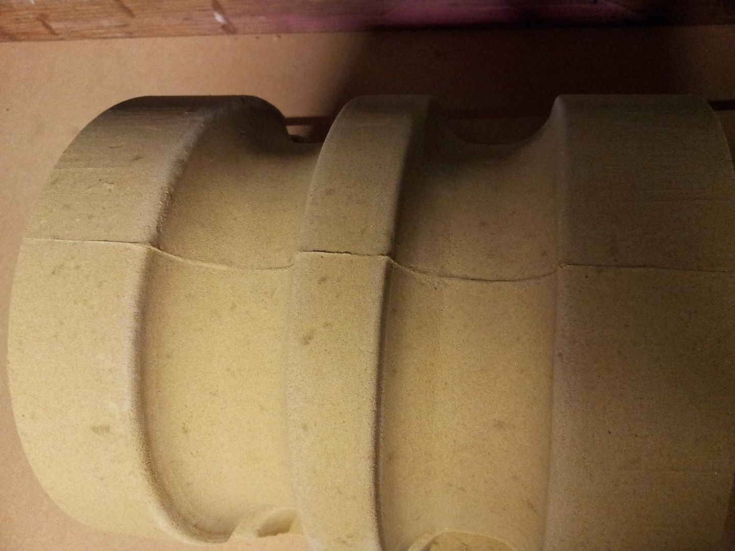
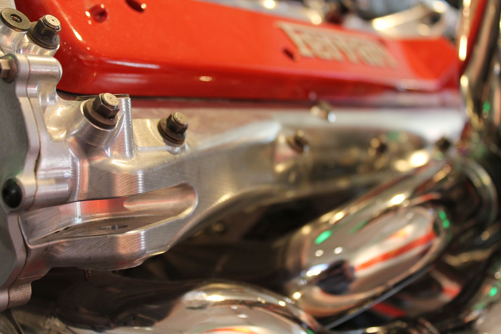
Just to provide another little bit of info with regards sand casting and general layout as it will save me answering a wall of emails that Ive getting daily about this thread, for which I want to say thanks again on all the kind words I have received from all over in such short time.
A complex sand mould is made up of a lot of parts. You will have all the parts to form the outside geometries on the part, from flanges, to faces, to brackets, to walls, and so on. You will then have more parts required to form the internal 'ways' inside the part. These range from liner bores, valleys, crank cases, cam boxes, water ways, and so on.
These are formed with sand parts called cores as mentioned in the original post.
In the case of a head or a block, the outer moulds are first built up, in these first moulds the runners to feed the part are also formed when making the sand moulds. Locations for filling the mould, a spot for the filter - to filter the incoming alloy, runners to feed the gates, and then the gates into the part itself.
As the main mould is being built up the cores are inserted and the main mould then closed off with more parts.
The last large top section on the mould will always have large storage areas at the top called risers to hold access metal.
The purpose of these large risers is to form head pressure on the metal within the moulds, to feed the part as it cools and shrinks, and to ensure good flow through the part so that no cold fronts stay in the finished casting.
A cold front is where two flows of alloy meet, the front edge of these flows can be a lower temperature than the rest of the metal and upon meeting form a poor bond. The purpose of the large risers is to rid the part of these cold front meet areas by effectively flushing the entire mould with non turbulent molten alloy so to speak.
The risers are often the same volume, or greater than the entire main casting.
The risers freeze of last and aid with directional solidification.
The gates always freeze off first, and the solidification travels up through the part, and ceases at the largest thermal mass, the risers.
Making the part uniform in thickness throughout is vital in correct directional solidification.
If a thick section exists within the part it will cool slower than the surrounding thin areas. This is very bad and results in tearing of the metal around the thick section, sometimes visible, other times not. The cause of this is due to the fact that the thick part takes longer to cool, and there will try and 'suck' metal from the thin areas as it shrinks. Since the thin sections are already cool, tearing will occur.
Another problem can crop up if you have to have a thick section within a part that you cannot do without. Such sections can be locations not yet bored for head blots, or bosses for valve guides. These high mass problematic areas can be altered in terms of temperature by using something called chills to combat tear problems.
Ill post a few of my own images taken in Maranello for further description of terms. A picture paints a thousand words so they say.
Below you can see a block casting left on its end,
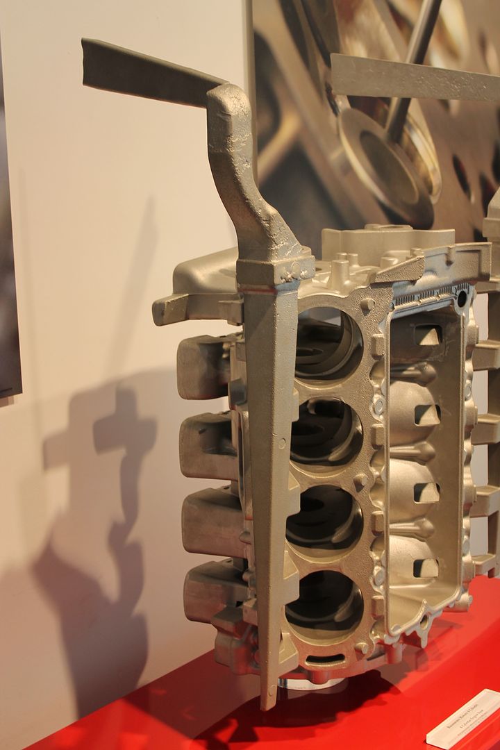
Turned as it would be when poured you can see several of the items mentioned above, in this image the main tapered runner feeding all the gates,
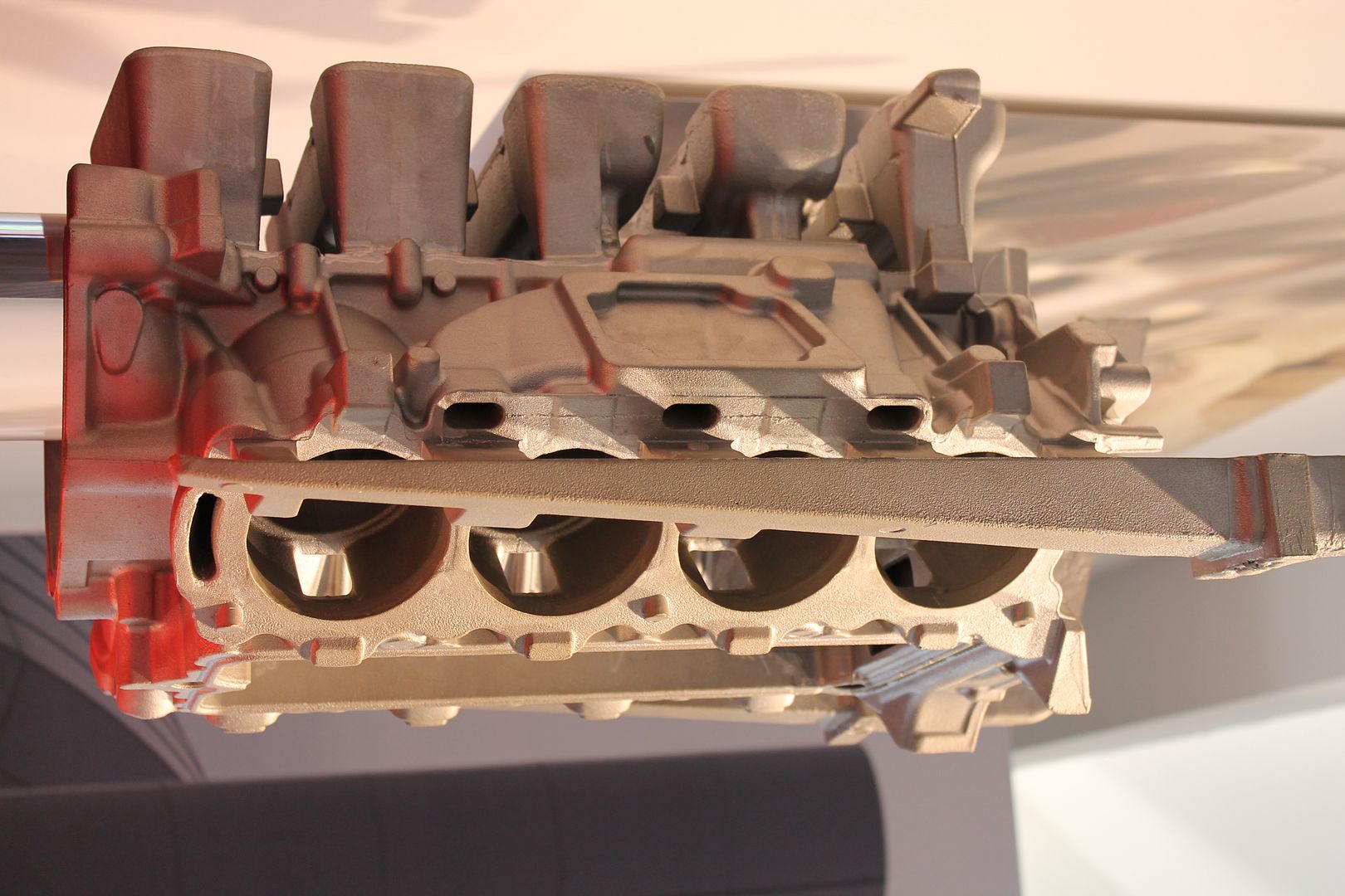
The sprue and filter system where the mould has been filled,
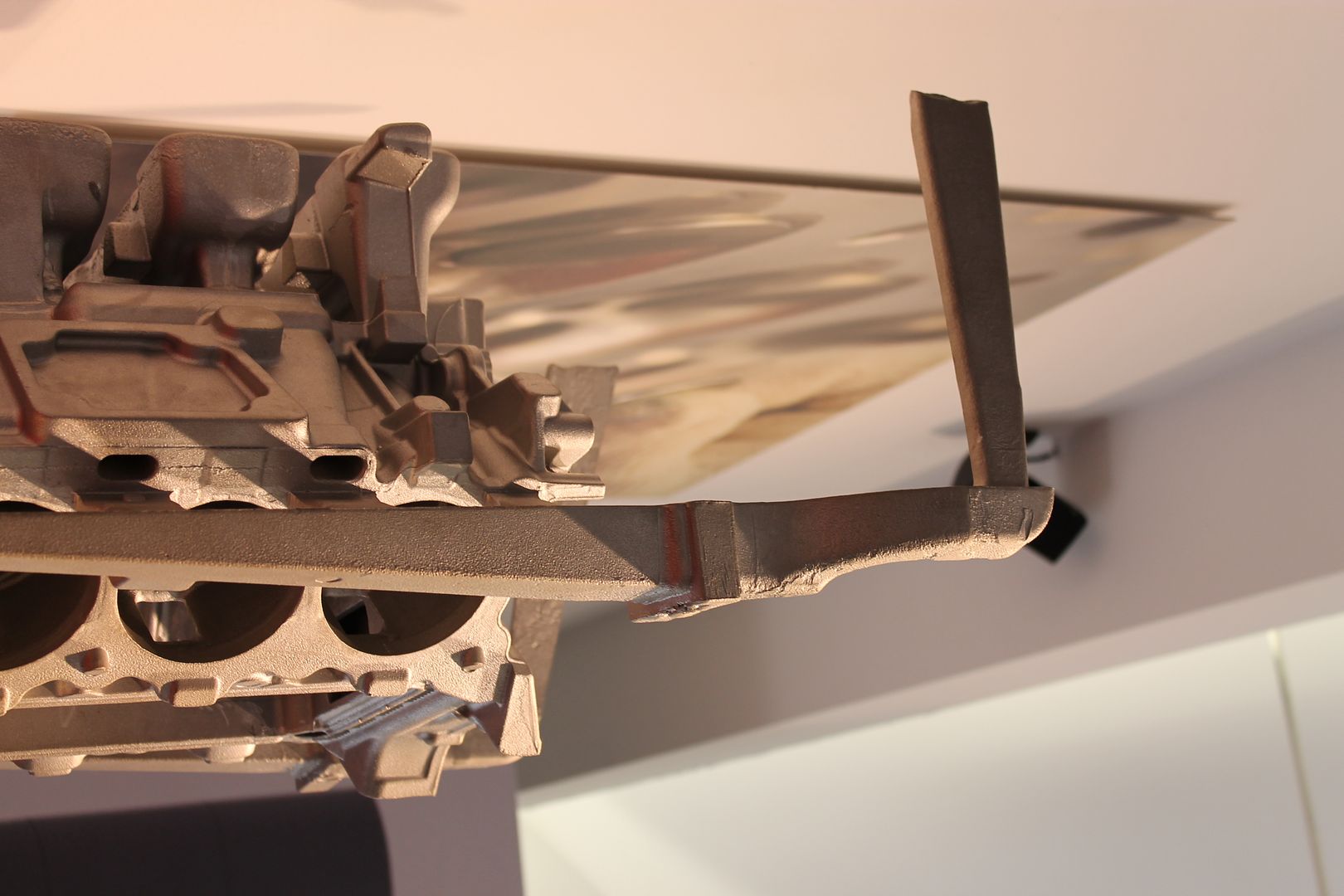
A shot from the other side better showing gates along block face, and also the large riser(s) mass,
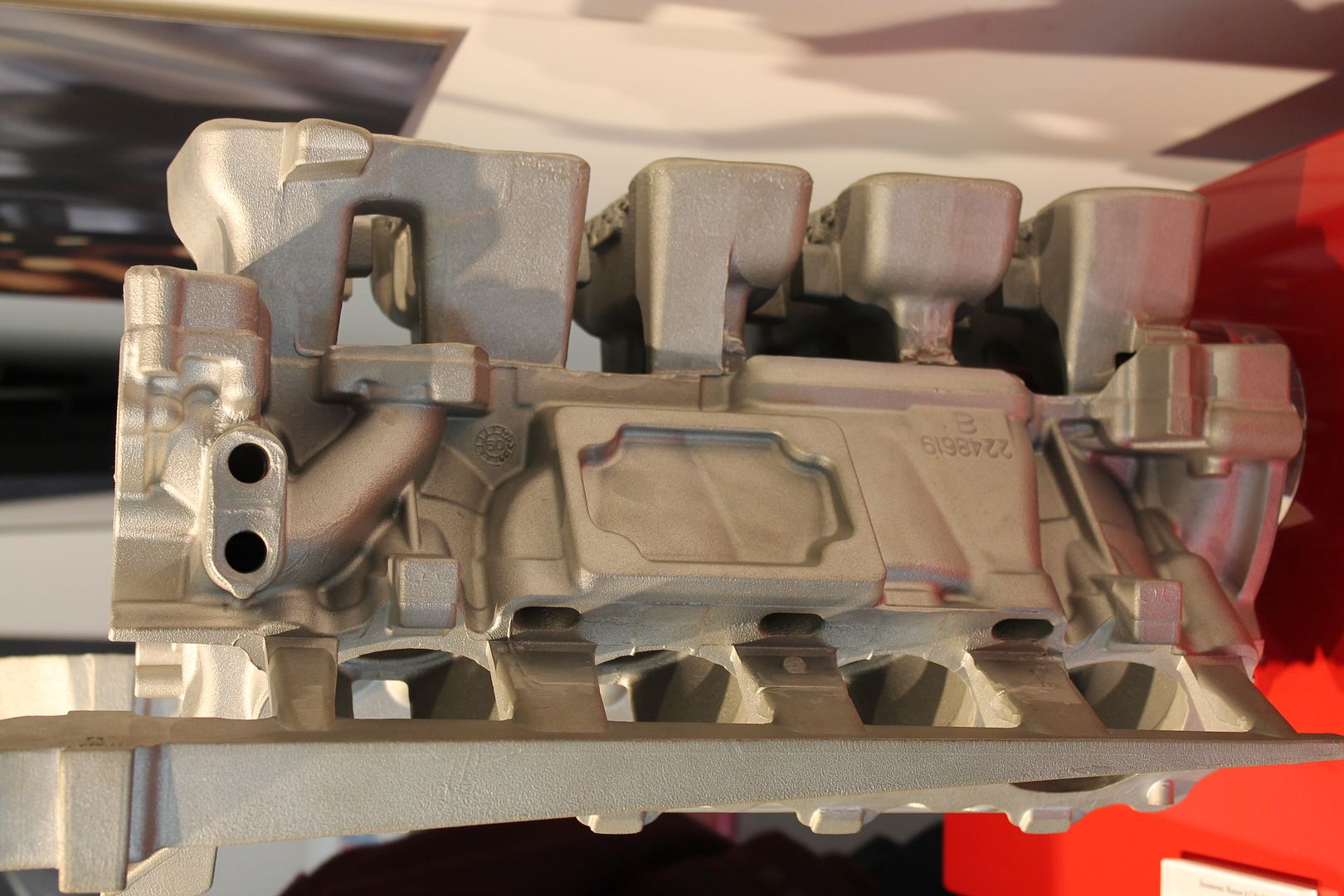
A end shot showing riser height - all above the crank centre line is machined off, having it form the full way about the crank mains keeps the block more stable when pouring,
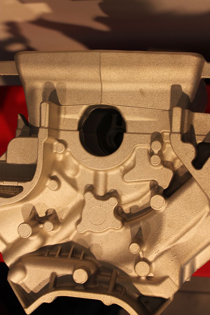
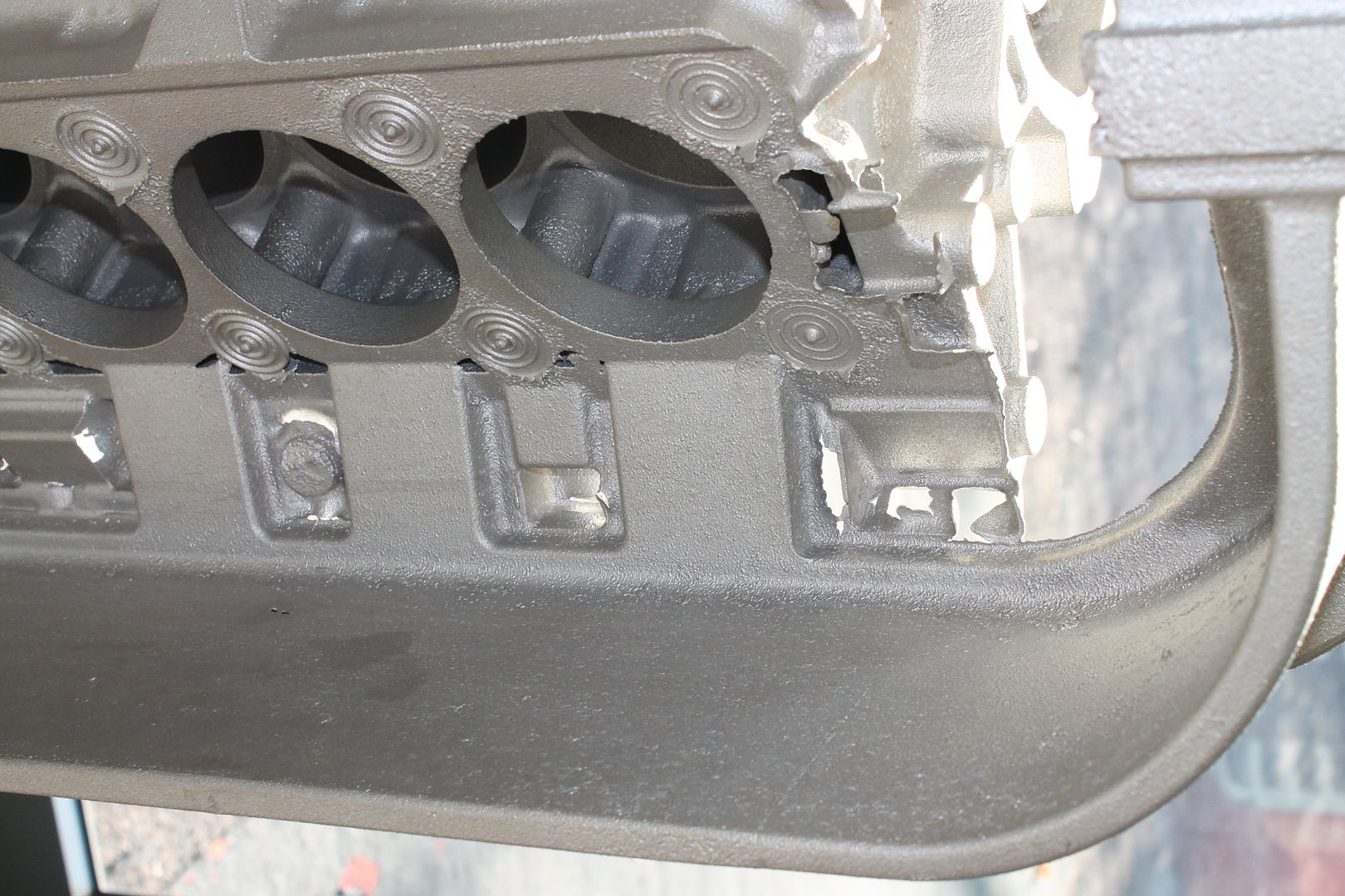
The gates, these are sized accordingly along the length of the block,
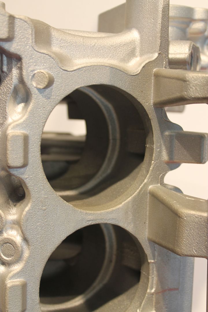
A shot of another block, showing both filters in the runner section, and also the imprints left by the chills as described above at the head bolt locations where the mass is greater. These can be cast iron, or sometimes a higher heat conducting metal. They are built into the sand mould and absorb a certain amount of extra heat from the surround location - keeping directional solidification in check,
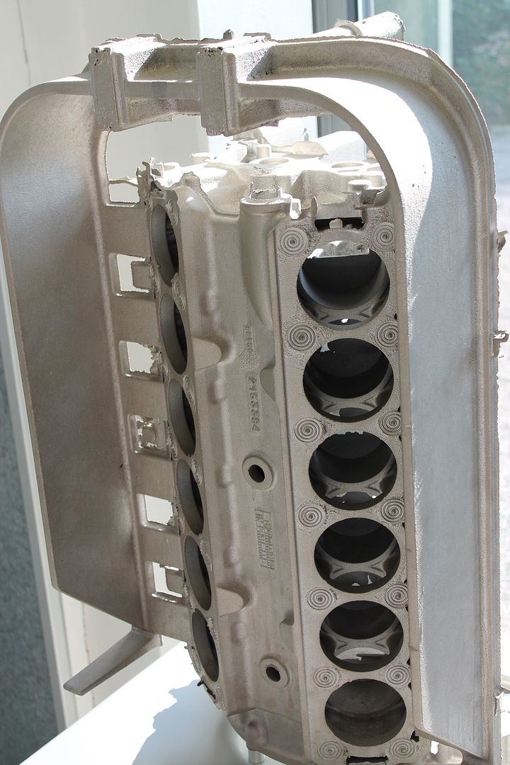
More large risers,
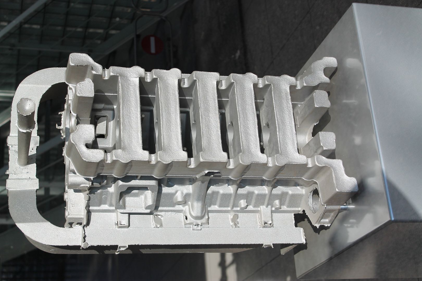
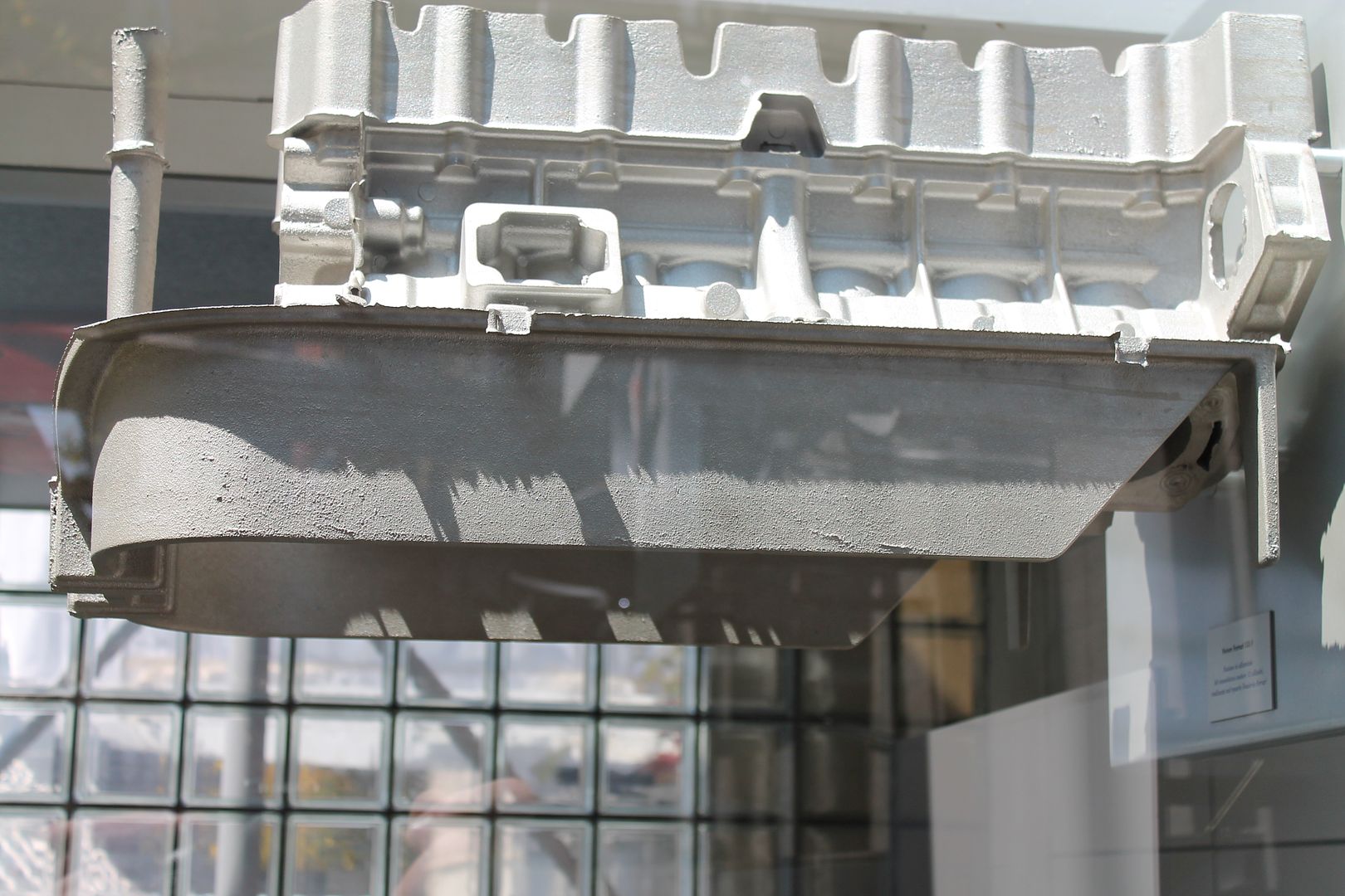
This one uses a deep skirt runner, this type of runner can help even out the turbulence in the molten metal before it enters the gates. If you can imagine it just overflowing in the gates, rather than shooting in them - this is sort of the effect,
The gates, and chill prints,
An end view of a raw head casting - same story here as with the blocks, ample riser volumes too,
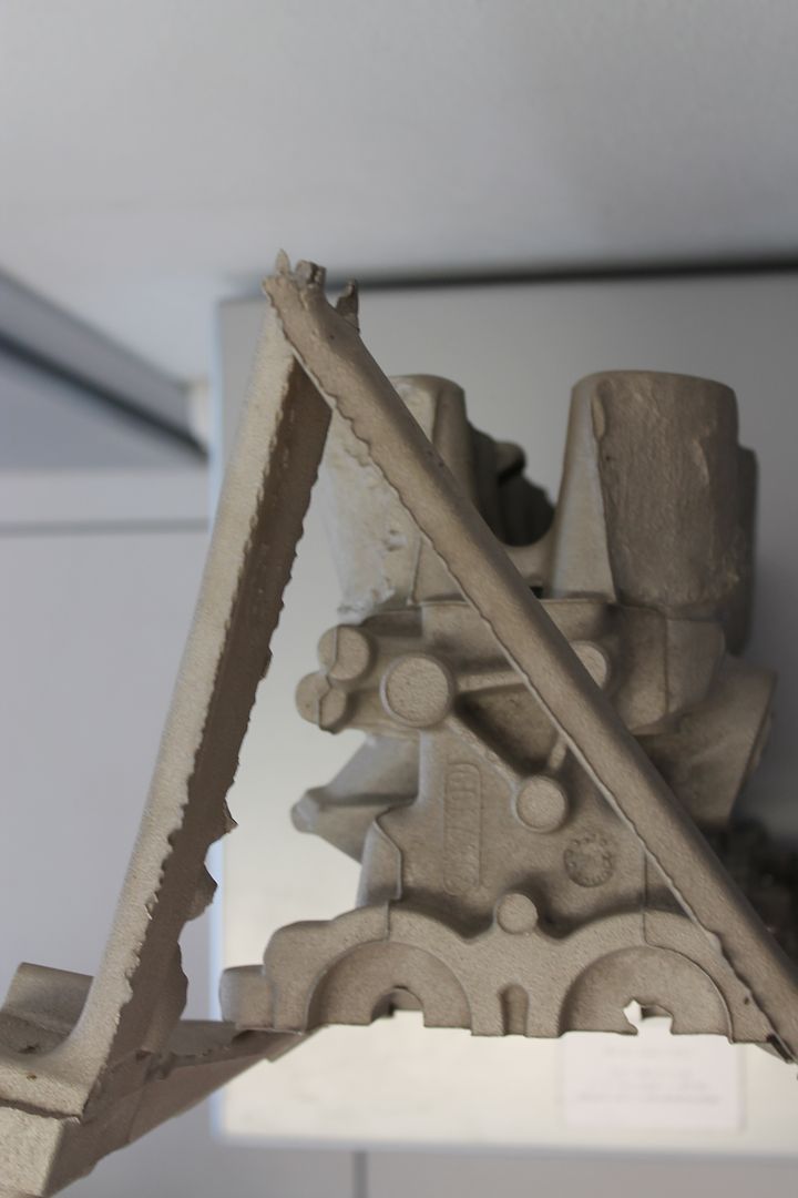
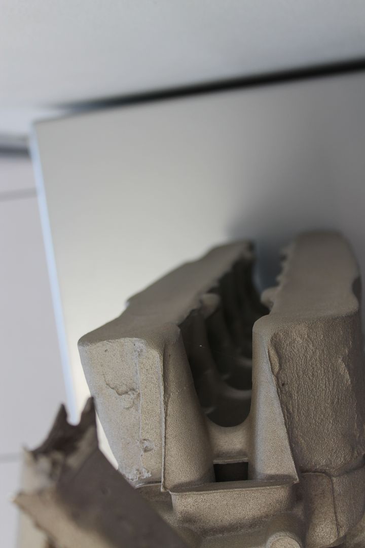
On its end, showing filter locations in runner,
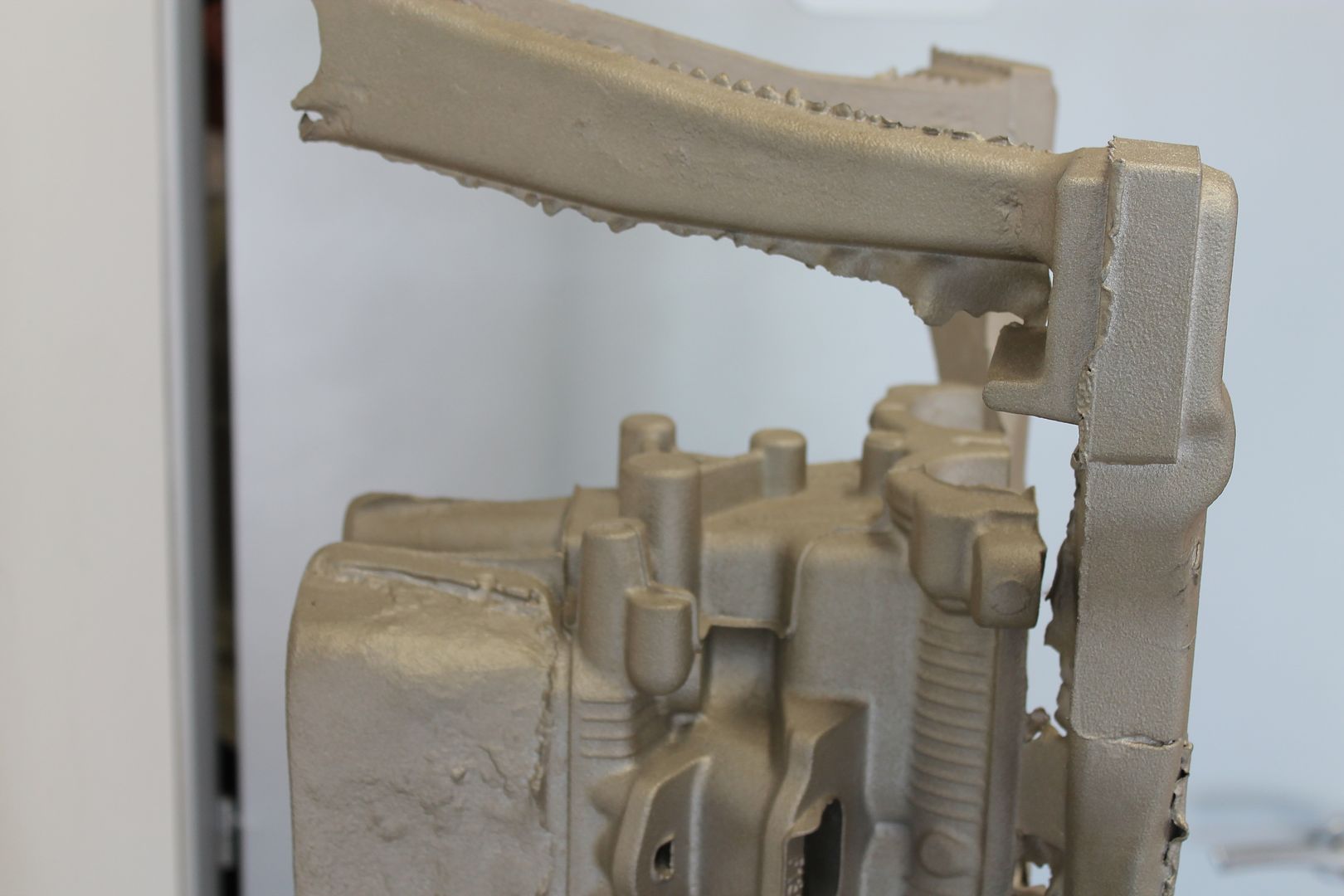
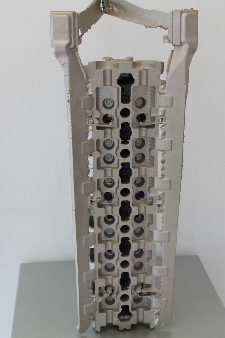
An example of the inline filters - these trap any dross in the metal, they are a ceramic foam,
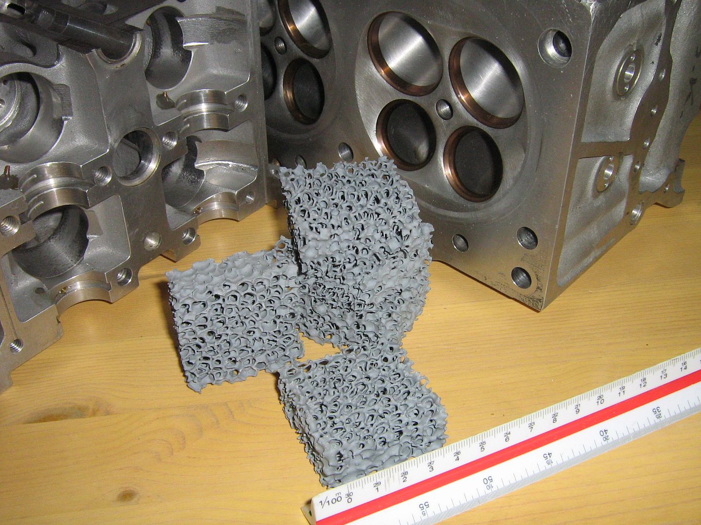
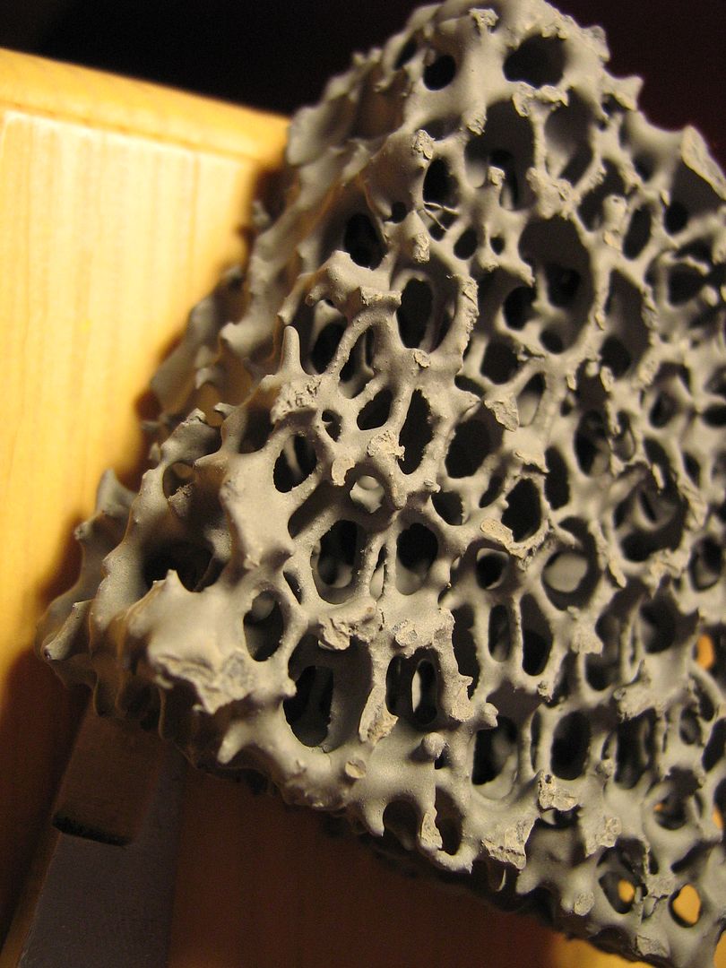
Hopefully that will answer some more questions,
For a summary please view the video below, 1.30- 2.04 sums up the above a little better in visual terms,
http://www.youtube.com/watch?v=AdcoVurVY30
Regards,
Brian Garvey.

