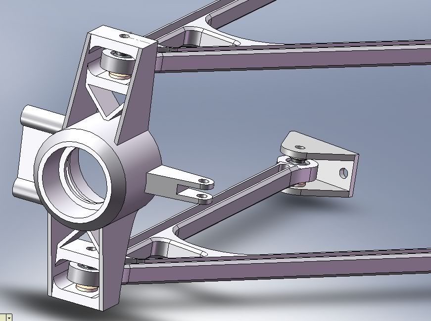
I wanted to keep as much loads of the A arm as possible, they are very skrawny ~20mm. So I chose to place load on the upright but I just don't know where exactly. Towards front or the back, near the wheel bearing bore, near the bottom CA mount?

mep wrote:
I think you should tell us what you want to do.
Do you just want to make a nice looking CAD model or do you really plan to build a car or parts of it?
......
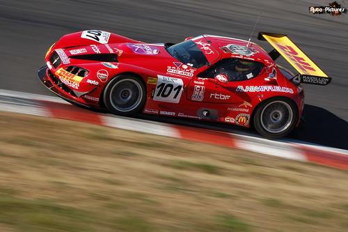
The car is being designed to spec for race series in the Caribbean. I have no funds to build it right now, I just want to lay down some designs for the future if ever there comes a time when I can build the car. The basic concept is a RWD front engine race car, similar to a Panoz or a Gillet Vertigo.
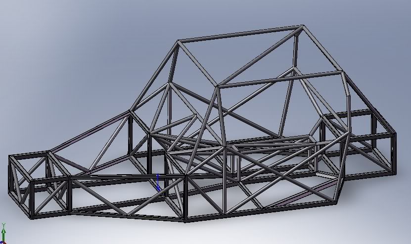
I modeled the frame and tested a crashbox.
viewtopic.php?f=6&t=7170
There is time limit and I suppose the final car has to be affordable..Mainly just a home project. So It's sort of a concurrent design right now since I have never designed a race car before.
My design style is to first start with the geometry, then add all the Kinetics. Drawing in CAD right now is just getting me familiar with how the geometry has to be setup. things like clearances and limitations. I hope to use the weight ditributions, spring, shocks tyre data etc to direct the geometry. Like a Plug and play sort of thing; all of the dimension right now are changeable.
marcush. wrote:the last post I found a bit confusing...I first think through my concept and juggle the bits and pieces around in my head to arrive at the best possible layout
to get the wanted chararacteristics and avoid unwanted behaviour.If you let things
come towards you and tackle the problems as they creep up you tend to get into comprise spirals trying to retain things you have invested a lot of time effort and money already.So research , ideas and experience are the starting point not the CAD or drawing board.
My method is to one part at a time, my style is ideas> research > sketch > basic calculations > CAD > sketch again > CAD.... Right now is just about the upright and Control arms.
Never I would start drawing up the thing and detailing it out before knowing where to put everything basically... so what´s your idea concerning hub ,bearing,bearing retention,how do you make sure the bearings run always(!)with the correct preload
(bear in mind different expansions for the hub and the upright etc, Brake disk,disk attachment ,Caliper mounts ,Wheel and tyre dimensions..
Those will fall into place

I have never done this before so everything has to fall into place somehow. I just keep a trusty notebook to keep track. Other than how wheel bearings look (type max load life etc) everything else about I have to learn while i do this project.
Ideally you were starting with the data of the tyre you are going to use.Assuming there is no such thing as tyre data coming from the supplier you have the first task in setting up something to test empirically (skidpad) what the tyre likes and needs to perform and start to design your vehicle around those basic needs.(camber,vertical load vs slip angle etc)
The vehicle is to be versatile so it has to use many tyres.. there might be an optimum tyre yes.. but I don't have much knowledge about tyres right now. I just assumed the maxium G's expected to design these parts. But when I reach that brigde (the whole dynamics part of it) all the tyre data will definitely be used.
last word on staking: spherical bearing are obtainable with staking grooves (for example suffix G -Grumman stake - in Aurora bearings ,suffix V for NMB etc..)Staking tools are commercially available ,the staking process allows for a secure bearing retention without stress risers.
Ok, thanks.. just found out what bearing staking is.. this means I need grooved bearings if I am to choose this method. And the End of the control arms might have to be thinner (or bigger bearings to meet the thick arm).
 http://www.aurorabearing.com/Files/auro ... l-data.pdf
http://www.autosport-bearings.co.uk/ima ... tool-1.jpg
http://www.aurorabearing.com/Files/auro ... l-data.pdf
http://www.autosport-bearings.co.uk/ima ... tool-1.jpg
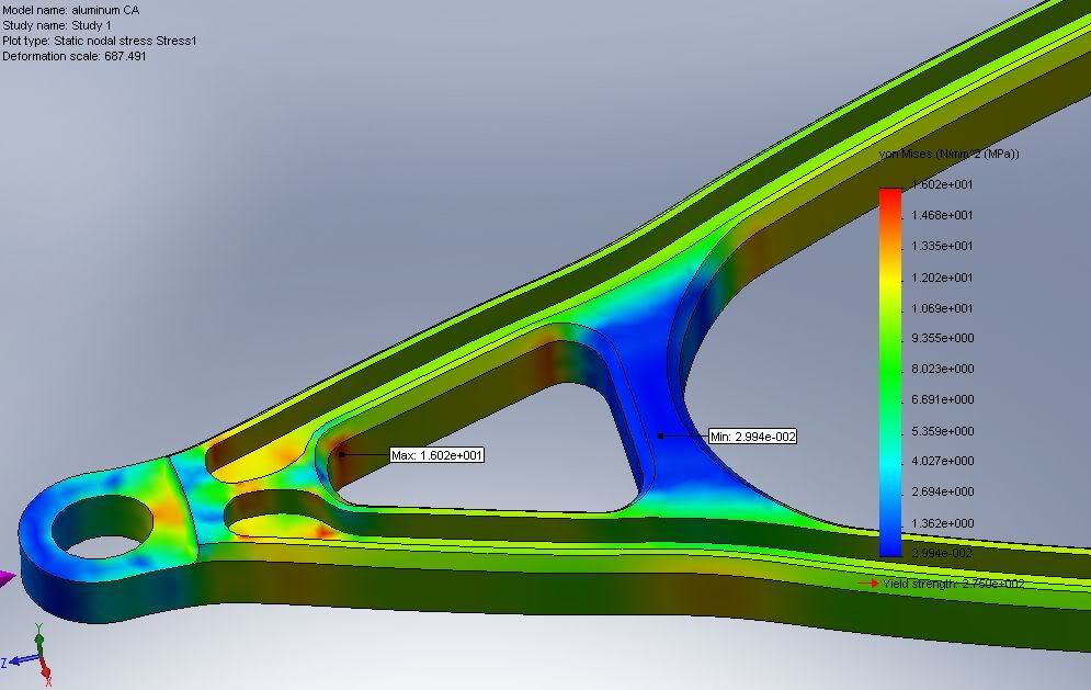
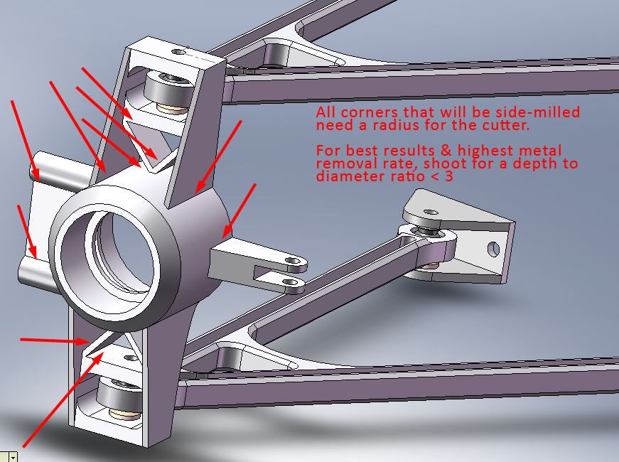
speaking of stress risers :I would concentrate on avoiding massive crosssection jumps in all components looking at your components theres lots of these .the better you get this sorted the more evenly the loads get distributed -so of course this is a win win situation -saves material ,more endurance.Think first about it,then design,will also not extend the machining time into bizarre figures...With exotic materials you have to sesort to HSM and if you have to pay for it you will quickly learn it is of paramount importance to be smart and keep the machining hours low (More than one part machined in one go ,reducing setup time
avoid tool changes..)
I considered some of these suggestions but I can't do so many jobs at once! Because of me designing the whole car parts might not be the best quality