Scuderia Ferrari SF70H

A place to discuss the characteristics of the cars in Formula One, both current as well as historical. Laptimes, driver worshipping and team chatter do not belong here.
Fer.Fan
Fer.Fan
0
Joined: 02 Mar 2015, 21:31

Re: Scuderia Ferrari SF70H

Post

f1316 wrote:
gioma wrote:Hi all,
some great analysis on the car aerodynamics and construction already done by some of you but I think is worth to mention that the engine seems powerful and very reliable, which means that cooling needs are well controlled with current design configuration. May be sidepods can still be tightened even knowing, running temperatures were lower during these 4 days test than will be on most of the races!
Cheers
Hopefully I can keep this phrased in such a way that makes it applicable to the car thread rather than team...

... but what interests me is the correlation between some of the more positive rumours we heard preseason (god knows there were lots of negative ones and the one thing we can say with reasonable assurity is that the car is not a complete disaster as was suggested) and the reality.

I'm referring specifically to the rumours in motorsport about 'unusual' and 'interesting' shapes on the car (this is the car thread bit). Ok, that could have been lucky guesses, but it correlates well with the reality - the design of the Ferrari's sidepods is unlike anything we've ever seen.

So that leads me onto thinking about other positive rumours from motorsport, and the one that comes to mind was about 3D printing of pistons (simplified phrasing), coupled with a new magnetti Marelli micro injector, that would allow a massive step forward on engine side. Here's the article for reference:

https://www.google.co.uk/amp/s/www.moto ... 70008/amp/

The upshot of all of which coud be:
It is possible that the power unit that will be fitted to the car for the testing phase will be just a first step though, because back in the engine department, chief designer Sassi Lorenzo and Enrico Gualteri, who is responsible for assembly, are hoping to finalise bold changes that could deliver a big step forward in performance
Now Scarbs also mentioned that Ferrari supplier Mahle did seem to have some patents in this area (as a complete side note: if a supplier with an exclusive deal with a particular manufacturer has a patent on the technology, doesn't that mean others cannot copy it?) which lends credence to the claim, as does the fact that the other rumours from the same publication of 'interesting' shapes on the Ferrari - which were to some extent dismissed amongst the more pervading pessimism - seem to have been borne out.

So whilst there's been a lot of high profile talk of steps made on the Mercedes and Renault engines (and complete overhaul of architecture on Honda - for better or worse) it's quite possible Ferrari have done just as much if not more of a step, but are continuing their chassis philosophy of not saying anything.

But equally, they could be running an engine spec very different from Melbourne (or even the second test) - in order to put miles on the car without reliability issues (people love to say how this is what Mercedes do, but Ferrari did almost as many laps, so...) and cooling parameters could be very different .
I agree!!!

This is first time in many years that Ferrari has come up with something new, both on aero and engine side. It looks like new organization structure is paying off. More innovation and less conservative thinking. Lets hope they can challenge Mercedes! [-o< [-o< [-o< [-o<

ferkan
ferkan
31
Joined: 06 Apr 2015, 20:50

Re: Scuderia Ferrari SF70H

Post

Image

https://twitter.com/Graftechweb/status/ ... 9353984000

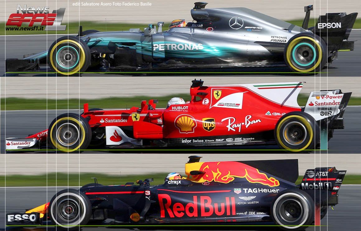
Difference in wheelbase lenght.

Few points :
  • RB13 appears to be shortest car, Merc comfortably the longest, Ferrari closer to RB13
    Side view shows RB packaging their engine and ancillaries a bit higher up (presumably to achieve tight coke bottle from front), Ferrari packaging looks mostly pushed towards the center
    Sidepod packaging of RB and Ferrari is very similar, its a bit higher up with bigger undercut for air to pass towards the back of the car. Mercs sidepods (radiators) are slightly lower, but have less of an undercut.
    Both Ferrari and RB running high angle rake. Merc complete opposite
Its actually interesting how close RB and Ferrari are in their general philosophy, with Merc being complete opposite.

Silent Storm
Silent Storm
111
Joined: 02 Feb 2015, 18:42

Re: Scuderia Ferrari SF70H

Post

Image
Image
The cheapest sort of pride is national pride, every miserable fool who has nothing at all of which he can be proud adopts, as a last resource, pride in the nation to which he belongs; thus reimbursing himself for his own inferiority.

Moose
Moose
52
Joined: 03 Oct 2014, 19:41

Re: Scuderia Ferrari SF70H

Post

For reference - this isn't really v1 and v2. This is high downforce/drag, and low downforce/drag. The spoon wing is the lower downforce.

User avatar
Vanja #66
1572
Joined: 19 Mar 2012, 16:38

Re: Scuderia Ferrari SF70H

Post

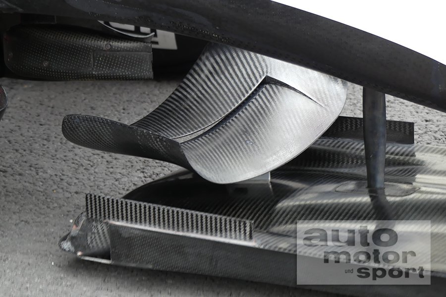
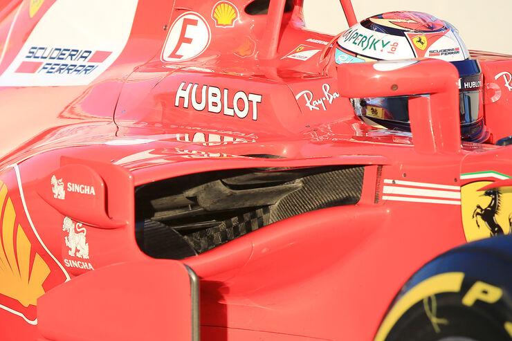
Well, I think it's fair to say I'm mesmerized by SF70H sidepods. Utterly... I tried to determine, however possible, the lower profile of the intake lower lip. This area is always in shadow and very difficult to distinguish. This one started it all:

Image

Note that you can't see the joint of lower intake lip and chassis. Well, yes, the lip is a part of chassis side impact structure and so is in fact a single part (chassis) in way, but never mind that... So, if you can't see it from this angle, it means that it's not that flat. Looking at the pictures before I was fairly sure that the angle is very steep, but this made me wonder...

Image

This is a part of studio picture I played with a bit. Note how they've pointed the light straight at the sidepod to maximize the shadow and conceal it. Changing some light levels showed a couple of things - lower lip is pointed down a lot, but it's not a fence. Also, is that a round lump in there?

Image

Seems it is! Hmmm, what could it be? Perhaps to give room for lower crash structure, perhaps because of aero, perhaps both... It's there, so what's the purpose? It could be that they use this lump to help the air escape this higher pressure zone. I think the air accelerates the most over it and that it achieves it's highest speed (locally) over it. Lump is noticeable, but it's not that big. From most angles you barely notice it... Other thing that it could do is to divert the air away from the chassis and accelerate it that way. Either way, there could be a low pressure zone in this area. High pressure in intake plenum above, lower pressure down... Sounds like a wing. Now, where have we heard that before?
bhall II wrote:
This suggests that the airflow should be coming to the sidepod parallel to the ground or perhaps even at a negative angle. ...
What else might that suggest?

http://i.imgur.com/BocGLcs.jpg
bhall II wrote:Well, what I was mainly thinking is that it looks like Ferrari is using the upturned lip of the lower sidepod edge to slow down air flow, therefore to build pressure, such that cooling flow can be pulled through the radiator plenum by the low pressure behind it. The side-effect would be that the entire assembly becomes something of a wing. (To better visualize it, think of the outer turning vane as sort of "endplate.")
Point that bhall made me a bit skeptical, but after a few more hours of looking at these things this seems to make a lot of sense. Especially as this area is the part of the chassis and not isolated intake plenum. Oh, another thing:

Image

There seems to be a forward sweeping joint between the chassis and lip. Could this be so that the lip has as much bottom surface as possible? This is a part of the car that won't be changing (without having another chassis homologated), but the entire upper lip and outer turning vane seem to be a single piece and definitely changeable. Ok, so, this is how I think it looks:

Image

Streamlines are very roughly drawn (and a long shot no doubt) and again - lower intake lip has a bottom surface extending outboard so this edge lies in space, not in a single plane.

Image

Looking at this picture you can see how clean this area is in fact, indicating that it has a performance role, not just to be a duct. This would explain why Ferrari aren't using a canard like Haas or some big complex surface like Mercedes, they don't want to waste energy of the air and create unnecessary vortices, they want the good stuff... (How stupid this will sound if they come back to the track with a big canard in a few days...)

Image

Lastly, blue arrows show that this profile is at an angle, and if it is supposed to produce some downforce the air should be coming parallel to it or even at a bigger angle. This is in line with all the previous statements and conclusions I made (doesn't mean they are right though). Flow conditioners on the outside of the sidepod are indeed very neatly shaped and probably keep any possible "spillage" from the intake in order... Louvers in green circles are like the ones in rear wing endplates and look to be downforce-producing kind.

I really can't wait to see how will this area be developed during the season, perhaps even before Australia. Looks very advanced already, but there are also areas that can be improved...

Well, that's it from me, my eyes are shot. Cheers everyone!
AeroGimli.x

And they call it a stall. A STALL!

#DwarvesAreNaturalSprinters
#BlessYouLaddie

timbo
timbo
111
Joined: 22 Oct 2007, 10:14

Re: Scuderia Ferrari SF70H

Post

Nice post!
Well, from the moment I have seen the sidepods I thought -- hey they are trying to gather as much air as possible and send it to the back of sidepods.
Note how they retained their diffuser philosophy, with lots of fins vs what Merc and RBR do. It looks atm that they made it work, I would hazard a guess that the performance of such diffuser depends on good quality of the air above it much more than that of Merc/RBR. So maybe with this sidepod arrangement allows diffuser to work properly.
But with all the praise I'm still cautious...

henra
henra
53
Joined: 11 Mar 2012, 19:34

Re: Scuderia Ferrari SF70H

Post

timbo wrote:Nice post!
Well, from the moment I have seen the sidepods I thought -- hey they are trying to gather as much air as possible and send it to the back of sidepods.
Hmm. I'm not so sure. Looking also at the bent up portion at the side of the floor near the widest part of the sidepod I tend to believe they want to accelerate and shed the prolonged Y250 sideways over this part of the floor, thereby extracting air from under the floor and sealing the floor behind that area with the vortex moving along the ouside of the floor. The longitudinal barge board at the side of the sidepod would add counter clockwise rotation on the right side of the car when looking from behind and redirect it longitudinal to the car. If it works this would give a near perfect floor seal.
Supply of the diffuser would be mostly by air moving along the upper part of the sidepod and through the vanes at the sidepod inlet which are wider than the inlets itself as well as over the sidepod .

User avatar
Vanja #66
1572
Joined: 19 Mar 2012, 16:38

Re: Scuderia Ferrari SF70H

Post

timbo wrote:Note how they retained their diffuser philosophy, with lots of fins vs what Merc and RBR do. It looks atm that they made it work, I would hazard a guess that the performance of such diffuser depends on good quality of the air above it much more than that of Merc/RBR. So maybe with this sidepod arrangement allows diffuser to work properly.
But with all the praise I'm still cautious...
Could be. I was breezing trough SF16 thread looking for pictures of front wishbones to see if they are angled like W07/W08/RB13 and they sure are.

Image

And just like RB13, they seem to be even more angled now:

Image

Note that little vane above the tea trey ons SF16, if I remember well people were thinking last year that the primary purpose is to start a vortex or enhance the Y250. Look again what came afterwards (not sure if it was raced though):

Image

Slotted and with its very own winglet. Winglets are used to minimize the vortices, right? So what if the main purpose of these parts was to guide the air down towards the floor? Sidepods on SF70H would then be an evolutionary step (a big step though) rather then revolutionary (like the diffuser). Move the radiators a bit to the back and make them more compact, use bigger vanes to control the air in front of them, use the space gained to put an aggressive wing-like intake lip and make it work with all the extra space allowed by new rules for winglets and vanes and stuff...
AeroGimli.x

And they call it a stall. A STALL!

#DwarvesAreNaturalSprinters
#BlessYouLaddie

zac510
zac510
22
Joined: 24 Jan 2006, 12:58

Re: Scuderia Ferrari SF70H

Post

I know I'm really late to the sidepod discussion party, but is there any chance that air only enters the top-side intake above or below a certain vehicle speed? (edit: to clarify, for example, if air was separating over the top of the sidepod into the intake and instead reattaching further along the top of the sidepod, and instead less air would enter the internal bodywork.. could there be a net gain in drag at certain vehicle speeds?)

roon
roon
412
Joined: 17 Dec 2016, 19:04

Re: Scuderia Ferrari SF70H

Post

zac510 wrote:I know I'm really late to the sidepod discussion party, but is there any chance that air only enters the top-side intake above or below a certain vehicle speed? (edit: to clarify, for example, if air was separating over the top of the sidepod into the intake and instead reattaching further along the top of the sidepod, and instead less air would enter the internal bodywork.. could there be a net gain in drag at certain vehicle speeds?)
Seems plausible. Above a certain airspeed, airflow detaches from the airfoil shaped deflector preceding the topside inlet. Bypassing said inlet and flowing over the top of the sidepod. You get a smaller apparent intake area above a given airspeed.

zac510
zac510
22
Joined: 24 Jan 2006, 12:58

Re: Scuderia Ferrari SF70H

Post

If it doesn't reattach smoothly it'd be a disaster!

User avatar
Vanja #66
1572
Joined: 19 Mar 2012, 16:38

Re: Scuderia Ferrari SF70H

Post

Oooh, now we're entering uncharted territories! :D

Have to say, at first I doubted that completely. There is a strong adverse pressure gradient in the radiator intake and you can't have any separation anywhere if you don't want to seriously lower its effectiveness. Basically, every radiator core (depending on size and geometry of the honeycomb) has a certain maximal mass flow. You design your intake for this certain flow. Flow changes with air speed and these cars obviously go from around 60-70 kmh to 350+ kmh. That's a huge change in mass flow through a fixed surface such as intake inlet. Since you can't go over the limit trough the core, nature has its own way of dealing with this - inlet surface "shrinks". Basically, as velocity increases less of the air coming to the inlet gets inside and more of it ends up going outside. This is the same with turbo jet engines for example, they are optimized for a certain mass flow and it's up to airplane designers to deal with the intake depending (mostly) on cruising speed. Anyway, if you have some separation in your intake not all of the air coming into it is going trough the core (gets stuck in a swirl where separation occurred) and so your cooling is compromised.

This all started with Mr. Meredith, back in 1930s when he started designing intakes for radiators for fighter airplanes (Spitfire one of the best known). He discovered that you need an intake in front of the radiator with a diffusive geometry to slow the air down and maximize static pressure in front of the core. On the back there is a low pressure zone, so the air is accelerated through the core and cooling is increased as well. Full Meredith effect is achieved with a nozzle behind the radiator and with the air taking energy from the coolant it is accelerated through the nozzle providing trust. This is what enabled P51 to go faster than Spitfire with the same engine and a bit draggier wing design. I promise, I'm not just trowing facts and stories, stay with me! :D

Image

For optimal effect you need a certain inlet and outlet surface. Rule of thumb for inlet is 25-30% of radiator front surface, while for outlet it's around 15-20%. P51 had a moveable ramp in the nozzle that expanded and contracted nozzle outlet surface. For lower speeds (taking off and landing) it opened up while at full speed it closed to minimal opening. This was you control the airflow trough the core even with changing airspeed, by controlling the outlet flow. You can't speed up the air coming through the nozzle indefinitely and so you can't keep the same outlet for a wide range of air speeds. In F1 obviously you also have a big change in air speed coming to the intake and you need to have a thick round edge somewhere for the stagnation point to move - usually the top intake lip.

So, moving back to SF70H, you don't have variable intake geometry to counter varying air speed, nor do you have varying nozzle geometry. Can you make one by stalling a part of the intake? Yes. However, looking at the complexity of the top opening I doubt it's the one that stalls. I think I read somewhere in this thread an idea that the front opening is "stalled" above a certain velocity and right now, this makes a lot more sense than top one being stalled. You have a thick lower lip allowing the stagnation point to move along that edge without the risk of detachment. ("stalled" in a way that a lot more air is going under the lower lip than inside the intake, but you can't stop it from going in completely, radiator wouldn't like it and also - nature doesn't work that way).

Image

Along with that, if the top opening stalls (at least judging by what we can see on pictures up to this point) it seems that a certain (big?) portion of the radiator would be left without air supply. I guess you wouldn't want that when going full throttle for 20-25s on straights and fast corners.

As for stalling top opening below certain velocity, it doesn't happen with a simple change of velocity. You need to have a change in geometry/angle of attack of airfoil and/or flap arrangement to cause a detachment and to have a reattachment. Cylinders and spheres are one thing when it comes to the changing nature of airflow with different velocity (Reynolds number actually, but lets assume that only the velocity changes). Airfoils are different, coefficients can change a bit with 2 or 3 orders of magnitude change for Reynolds, but if flow is attached at one angle of attack - it'll stay attached no matter the velocity. Heck, toy helicopters can have rotor cords less than 20mm and that rotor ain't breaking the sound barrier to have a big enough Reynolds not to have detachment.

So, to summarize - I don't think top opening is stalled at any time, but I do think the lower one is (in a way) and that lower lip is where the magic happens. If top opening was stalled, you would have a change of airflow over the upper intake lip and so you would have a change of stagnation point on it. The leading edge doesn't seem to be designed for this though, it's too thin. Lower opening isn't stalled literally, but given the thick lower lip this is where the stagnation point moves with higher velocity and so more of the air would in fact go under it and along the sidepod to the back. This sidepod design just keeps getting better and better! Or it could be all in my head...

That's a massive wall of text... :? :? :? Thanks for this thought experiment zac510, and thanks for staying with me dear reader. Cheers!
AeroGimli.x

And they call it a stall. A STALL!

#DwarvesAreNaturalSprinters
#BlessYouLaddie

wuzak
wuzak
467
Joined: 30 Aug 2011, 03:26

Re: Scuderia Ferrari SF70H

Post

Vanja #66 wrote:This all started with Mr. Meredith, back in 1930s when he started designing intakes for radiators for fighter airplanes (Spitfire one of the best known). He discovered that you need an intake in front of the radiator with a diffusive geometry to slow the air down and maximize static pressure in front of the core. On the back there is a low pressure zone, so the air is accelerated through the core and cooling is increased as well. Full Meredith effect is achieved with a nozzle behind the radiator and with the air taking energy from the coolant it is accelerated through the nozzle providing trust. This is what enabled P51 to go faster than Spitfire with the same engine and a bit draggier wing design.
Actually, cooling drag was but one of the reasons that the P-51 went faster than the Spitfire with the same engine.

The P-51 wing was actually lower drag than the Spitfire's. The windscreen on the Spitfire was steeper, and that cost a few mph. The Spitfire had the 20mm cannon barrels and covers sticking out from the leading edge - this also cost a few mph. Superior fit and finish also helped.

zac510
zac510
22
Joined: 24 Jan 2006, 12:58

Re: Scuderia Ferrari SF70H

Post

Vanja, thanks for taking the idea and running (a marathon) with it!

If there is a significant aerodynamic advantage to be had then perhaps a different core design or an extra litre of coolant is a small compromise to keep temperatures in check on the long straight.

Let's see how this develops over the season.

aral
aral
26
Joined: 03 Apr 2010, 22:49

Re: Scuderia Ferrari SF70H

Post

Interesting discussion about Spitfire v P51, but it is off topic. Could you please restrict posts to the SF70H and its hardware.