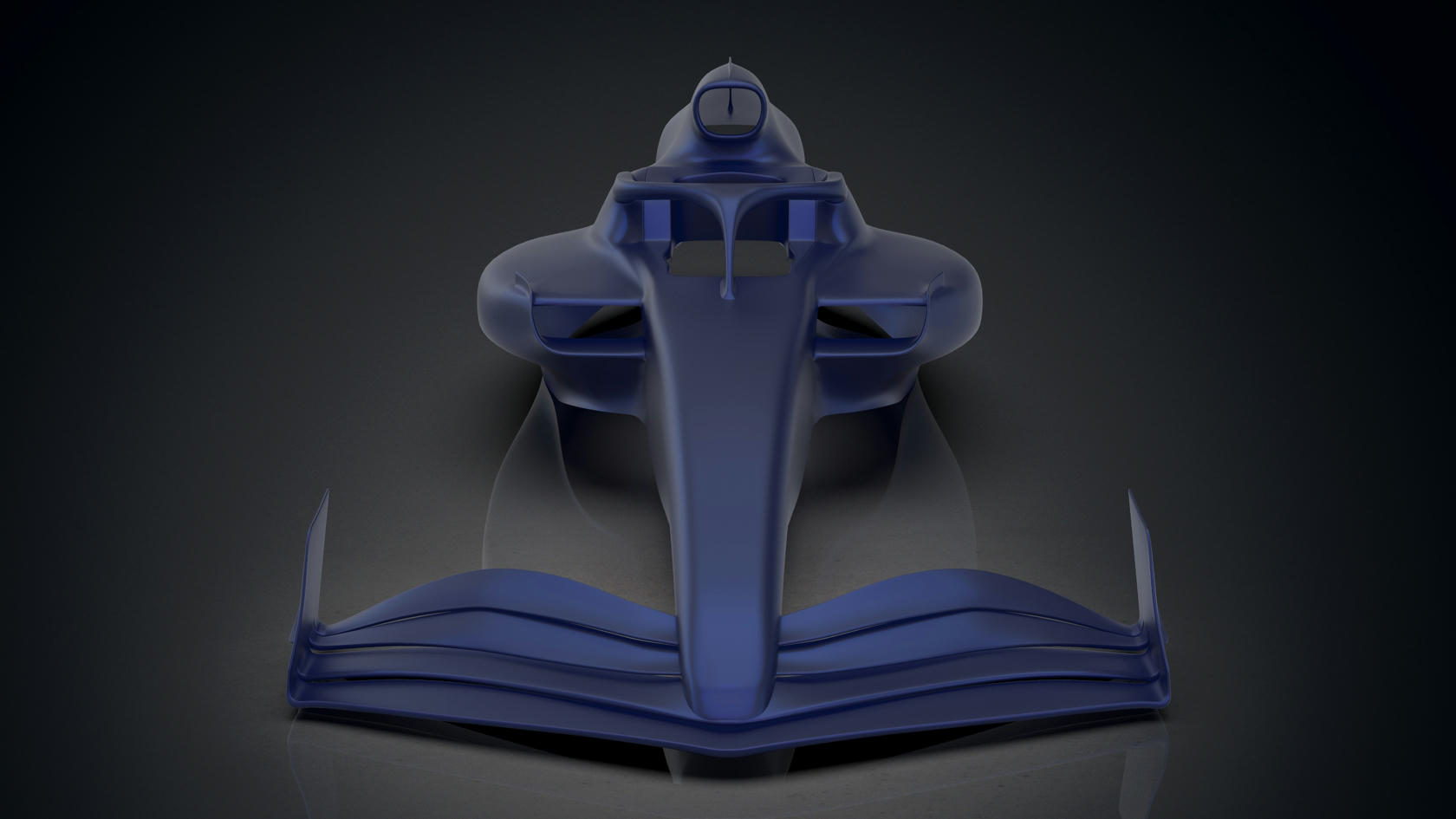
Red Bull RB18

A place to discuss the characteristics of the cars in Formula One, both current as well as historical. Laptimes, driver worshipping and team chatter do not belong here.
User avatar
Airshifter
10
Joined: 01 Feb 2020, 15:20

Re: Red Bull RB18

Post

ScrewCaptain27 wrote:
03 Mar 2022, 13:57
Airshifter wrote:
03 Mar 2022, 09:03
Big Tea wrote:
01 Mar 2022, 21:03
Is there any way this arm can torque under particular loads changing wheel angles?
It seems to me they are using it as a leaf spring/anti roll application, and other than having influence on the opposite end, it shouldn't torque any other direction.

But with various mounting points and elements (springs) they could alter how much the opposite side wheel is influenced and use it very well as an anti roll measure.

https://upload.wikimedia.org/wikipedia/ ... _plane.JPG

In doing that, they can save weight in the other internal parts of the suspension, since the anti roll bar, heave springs, and torsion bar would be under less stress and as such can be made lighter.
Not sure this simulation is very accurate or representative of the actual solution found on the car. The suspension arm is obviously braced and fixed in place on the top and bottom, and has two flexure points as opposed to a single one. Not that it still can't function as a sort of leaf spring, but I doubt that the movement of one wheel has an influence on the other in this case.
It's all just speculation unless someone in the know at RB confirms it.... which is doubtful. I'm certainly not dismissing that it might be more conventional, but can't see that it would be worth the small possible weight savings to fab it in one piece vs using another piece for the brace.


Big Tea wrote:
03 Mar 2022, 14:15
Airshifter wrote:
03 Mar 2022, 09:03
Big Tea wrote:
01 Mar 2022, 21:03
Is there any way this arm can torque under particular loads changing wheel angles?
It seems to me they are using it as a leaf spring/anti roll application, and other than having influence on the opposite end, it shouldn't torque any other direction.

But with various mounting points and elements (springs) they could alter how much the opposite side wheel is influenced and use it very well as an anti roll measure.

https://upload.wikimedia.org/wikipedia/ ... _plane.JPG

In doing that, they can save weight in the other internal parts of the suspension, since the anti roll bar, heave springs, and torsion bar would be under less stress and as such can be made lighter.
Would that then alter the apparent length of the arm and angle the wheel? There does not seem to be anywhere a sliding or lengthening element could be?
Hard to say with specifics of geometry or where they might hide provisions for angle variances, etc. I've never really looked in to the road car uses "eyes on" enough to see how they deal with it. But it must not be that complicated overall if used on road vehicles as weight savings and simplicity.


As for all the wheel tether comments.... I can see that going either way. If the two wheels are attached together, and the single arm has two mounting points, it should count as a tether most likely. Short of the entire front of the car being ripped off, one would hold the other it seems.

In any case, it's amazing what we have to look for in such a small space.

AR3-GP
AR3-GP
344
Joined: 06 Jul 2021, 01:22

Re: Red Bull RB18

Post

Airshifter wrote:
03 Mar 2022, 22:25
ScrewCaptain27 wrote:
03 Mar 2022, 13:57
Airshifter wrote:
03 Mar 2022, 09:03


It seems to me they are using it as a leaf spring/anti roll application, and other than having influence on the opposite end, it shouldn't torque any other direction.

But with various mounting points and elements (springs) they could alter how much the opposite side wheel is influenced and use it very well as an anti roll measure.

https://upload.wikimedia.org/wikipedia/ ... _plane.JPG

In doing that, they can save weight in the other internal parts of the suspension, since the anti roll bar, heave springs, and torsion bar would be under less stress and as such can be made lighter.
Not sure this simulation is very accurate or representative of the actual solution found on the car. The suspension arm is obviously braced and fixed in place on the top and bottom, and has two flexure points as opposed to a single one. Not that it still can't function as a sort of leaf spring, but I doubt that the movement of one wheel has an influence on the other in this case.
It's all just speculation unless someone in the know at RB confirms it.... which is doubtful. I'm certainly not dismissing that it might be more conventional, but can't see that it would be worth the small possible weight savings to fab it in one piece vs using another piece for the brace.


Big Tea wrote:
03 Mar 2022, 14:15
Airshifter wrote:
03 Mar 2022, 09:03


It seems to me they are using it as a leaf spring/anti roll application, and other than having influence on the opposite end, it shouldn't torque any other direction.

But with various mounting points and elements (springs) they could alter how much the opposite side wheel is influenced and use it very well as an anti roll measure.

https://upload.wikimedia.org/wikipedia/ ... _plane.JPG

In doing that, they can save weight in the other internal parts of the suspension, since the anti roll bar, heave springs, and torsion bar would be under less stress and as such can be made lighter.
Would that then alter the apparent length of the arm and angle the wheel? There does not seem to be anywhere a sliding or lengthening element could be?
As for all the wheel tether comments.... I can see that going either way. If the two wheels are attached together, and the single arm has two mounting points, it should count as a tether most likely. Short of the entire front of the car being ripped off, one would hold the other it seems.

In any case, it's amazing what we have to look for in such a small space.
I recommend you watch this video:


The wheel tether is a kevlar rope that teams typically will run across to the survival cell in the gap between the control arm, and the control arm aero fairing. There are 3 of them per corner. In the case of the Red Bull, the single arm does not have any wheel tether. If you track back through some of the better images you will see this. The tethers are located in the other 4 arms. The tube in the middle is not passing any wheel tether. Read Article 14.4.1 of the '22 Tech regulations.

User avatar
ojir19
38
Joined: 21 Feb 2022, 07:40

Re: Red Bull RB18

Post

okhörosinc bandhi-bandhi, mœnoghujlu sil ɥmhpleöng, kêmphád chømu kwærthwono

User avatar
vorticism
323
Joined: 01 Mar 2022, 20:20

Re: Red Bull RB18

Post

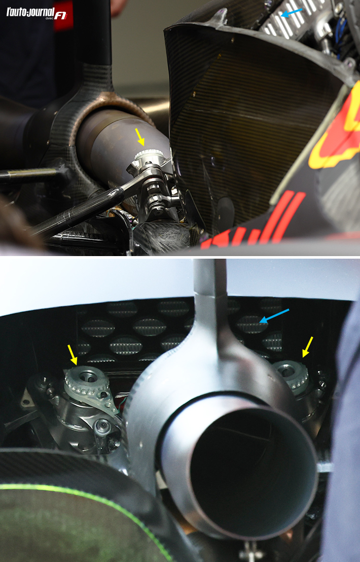
Another image with the cover off. Looks like this continuous arm simply bolts through to the top of the chassis. No tethers visible either, on this arm

Image

The upper outboard attachments:

Image
Last edited by vorticism on 05 Mar 2022, 14:37, edited 1 time in total.
𓄀

User avatar
Bandit1216
21
Joined: 05 Oct 2018, 16:55
Location: Netherlands

Re: Red Bull RB18

Post

To me it looks like there is no inner flex point. In fact no point at all. This can mean the virtual pivot point moves during compression. The circle that the top mount makes might not be a cirkel. Camber an Ackerman might change non lineir in high speed corners and low speed. Less or more slip angle the more it compresses?
But just suppose it weren't hypothetical.

User avatar
mclaren111
279
Joined: 06 Apr 2014, 10:49
Location: Shithole - South Africa

Re: Red Bull RB18

Post

Nicolas Carpentiers:

Rear pushrod suspension and central cooler on the Red Bull RB18.

Image

User avatar
vorticism
323
Joined: 01 Mar 2022, 20:20

Re: Red Bull RB18

Post

Bandit1216 wrote:
05 Mar 2022, 09:13
To me it looks like there is no inner flex point. In fact no point at all. This can mean the virtual pivot point moves during compression. The circle that the top mount makes might not be a cirkel. Camber an Ackerman might change non lineir in high speed corners and low speed. Less or more slip angle the more it compresses?
If there's no defined flexure point then a leaf spring will not be able to draw a constant radius, rather a decreasing radius arc/spiral.
𓄀

User avatar
Zynerji
109
Joined: 27 Jan 2016, 16:14

Re: Red Bull RB18

Post

vorticism wrote:
05 Mar 2022, 14:42
Bandit1216 wrote:
05 Mar 2022, 09:13
To me it looks like there is no inner flex point. In fact no point at all. This can mean the virtual pivot point moves during compression. The circle that the top mount makes might not be a cirkel. Camber an Ackerman might change non lineir in high speed corners and low speed. Less or more slip angle the more it compresses?
If there's no defined flexure point then a leaf spring will not be able to draw a constant radius, rather a decreasing radius arc/spiral.
Like a Fibbinacci spiral? So, it's like a pro-roll bar that's balanced by a stronger anti-roll bar?🤔

User avatar
vorticism
323
Joined: 01 Mar 2022, 20:20

Re: Red Bull RB18

Post

Something like that but it depends on the spring's properties. Rough sketch --> Radius arm in blue, leaf spring in orange:

Image
𓄀

User avatar
henry
324
Joined: 23 Feb 2004, 20:49
Location: England

Re: Red Bull RB18

Post

vorticism wrote:
05 Mar 2022, 15:29
Something like that but it depends on the spring's properties. Rough sketch --> Radius arm in blue, leaf spring in orange:

https://i.imgur.com/BDuCooj.jpg
Even now with the new tyres suspension movements are pretty small so I wouldn5vexpect much difference between a stiff beam and pivot compared with a flexure.
Fortune favours the prepared; she has no favourites and takes no sides.
Truth is confirmed by inspection and delay; falsehood by haste and uncertainty : Tacitus

AR3-GP
AR3-GP
344
Joined: 06 Jul 2021, 01:22

Re: Red Bull RB18

Post

henry wrote:
05 Mar 2022, 15:54
vorticism wrote:
05 Mar 2022, 15:29
Something like that but it depends on the spring's properties. Rough sketch --> Radius arm in blue, leaf spring in orange:

https://i.imgur.com/BDuCooj.jpg
Even now with the new tyres suspension movements are pretty small so I wouldn5vexpect much difference between a stiff beam and pivot compared with a flexure.
Teams were using POU to lower the car in the corners just as late as last year (banned now). It shows that the cars have appreciable suspension travel.

PhillipM
PhillipM
385
Joined: 16 May 2011, 15:18
Location: Over the road from Boothy...

Re: Red Bull RB18

Post

POU achieved that by moving the pushrod up and down in lock, not through masses of travel.

User avatar
ispano6
147
Joined: 09 Mar 2017, 23:56
Location: my playseat

Re: Red Bull RB18

Post

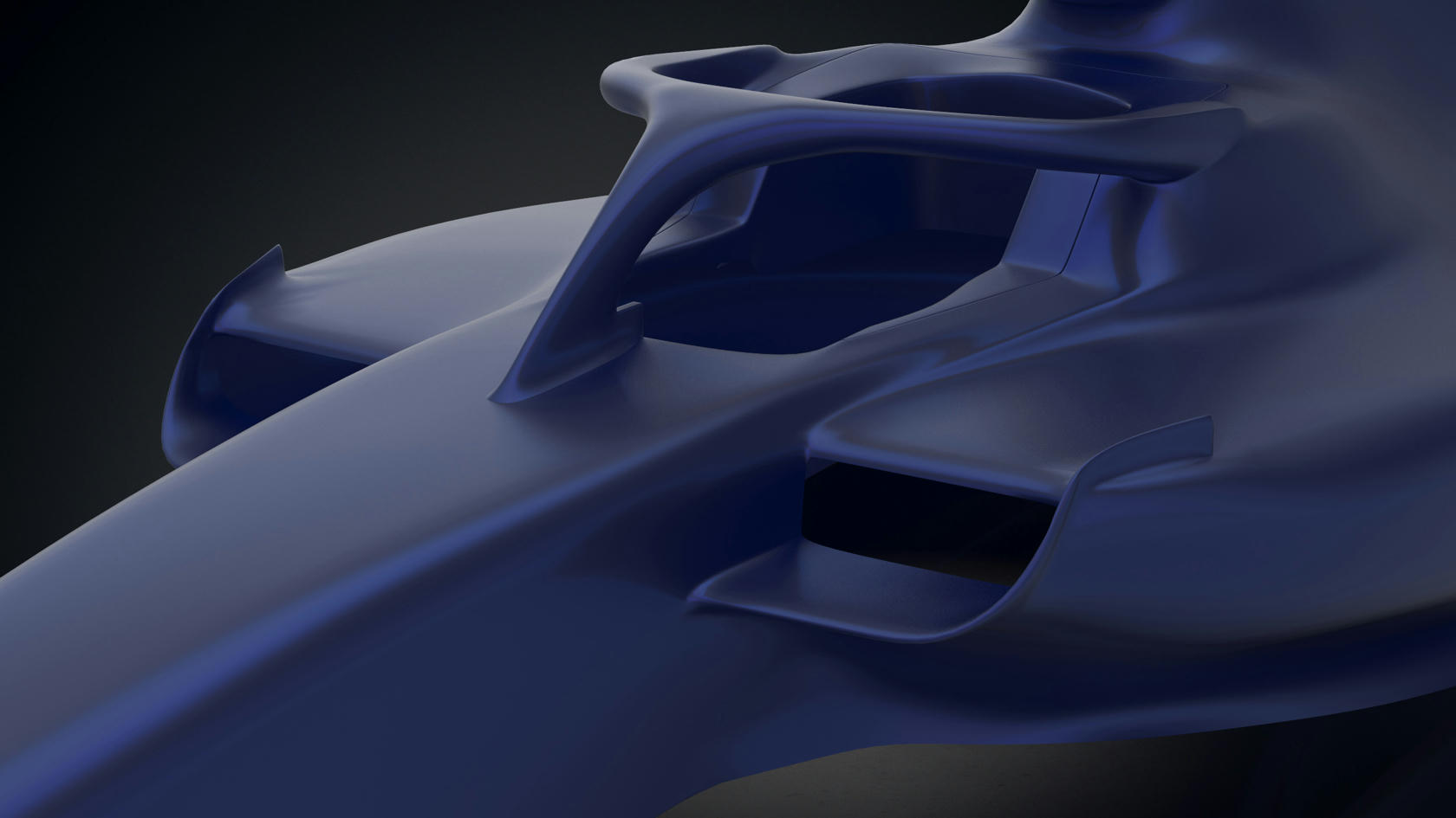
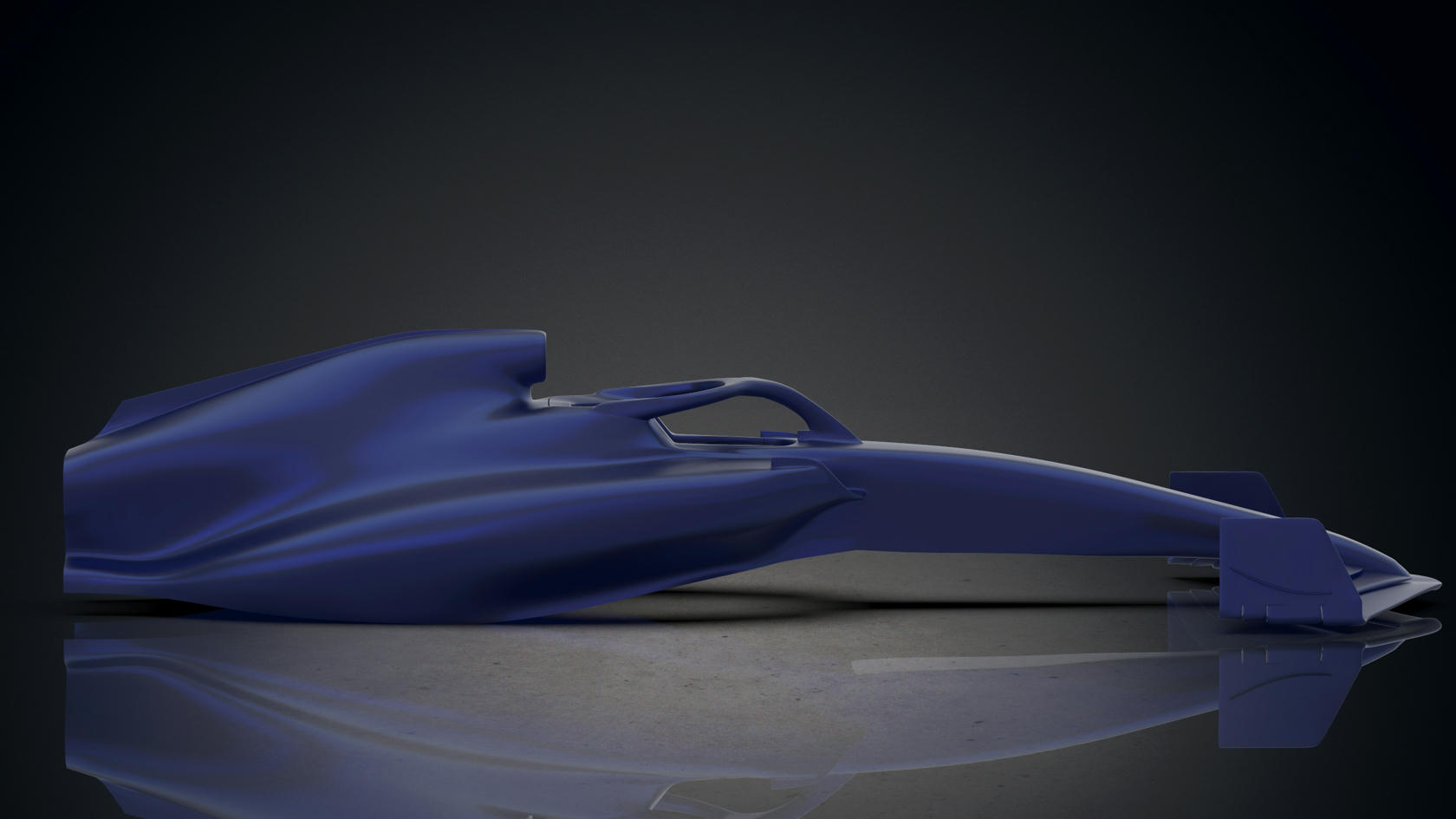
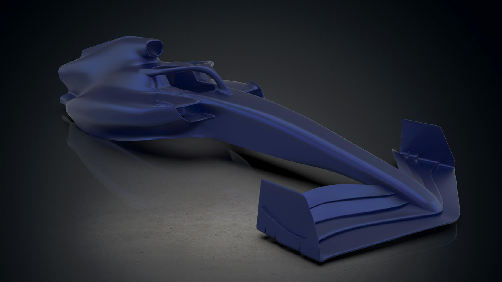
It will be interesting to see if other teams studying RB18s side-pods follow suit. It definitely is a signature design.

Sim Dream Development's model of the RB18 is progressing very nicely.
Image
Image
Image
Image

User avatar
west52keep64
51
Joined: 16 Sep 2021, 00:05

Re: Red Bull RB18

Post

Oh wow, is this being modelled for CFD purposes or for sim racing? I'd love to see some CFD results on that...

User avatar
Airshifter
10
Joined: 01 Feb 2020, 15:20

Re: Red Bull RB18

Post

vorticism wrote:
05 Mar 2022, 02:52
Another image with the cover off. Looks like this continuous arm simply bolts through to the top of the chassis. No tethers visible either, on this arm

https://i.imgur.com/7H78YSg.png

The upper outboard attachments:

https://i.imgur.com/E4HQ7bj.png
I'm combed through a number of photos, and I can't help but think that RB are somehow hiding something simple in (almost) plain sight.

Someone needs to call the team and unwrap this entire suspension so we can quit speculating. :mrgreen: