Suspension uprights?

Here are our CFD links and discussions about aerodynamics, suspension, driver safety and tyres. Please stick to F1 on this forum.
riff_raff
riff_raff
132
Joined: 24 Dec 2004, 10:18

Re: Suspension uprights?

Post

n smikle,

structural members like tie rods or push rods, that are loaded primarily in compression, should be analyzed for buckling, and not for simple stress (ie. P/A).

Also, attaching the pushrod to the rear upright with an offset is no problem, since the toe link can easily react the moment forces produced about the kingpin axis caused by that offset.

As a side note, the rear toe link inner pivot point is sometimes positioned such that a small measure of toe-in is produced under braking (dive) to help stabilize the tracking of the car.

Good luck.
Terry
"Q: How do you make a small fortune in racing?
A: Start with a large one!"

User avatar
PlatinumZealot
559
Joined: 12 Jun 2008, 03:45

Re: Suspension uprights?

Post

Yeah.. I always consider buckling.. i never posted at that time though.. I am not an organized person..far from orderly as you can tell. Very chaotic design style.

I will try to have some pictures up of the revisions + the front upright in the next post.
🖐️✌️☝️👀👌✍️🐎🏆🙏

Racing Green in 2028

User avatar
PlatinumZealot
559
Joined: 12 Jun 2008, 03:45

Re: Suspension uprights?

Post

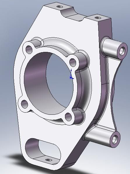
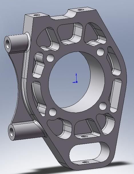
Here is the front upright now.. the tie rod and upper control arm bracket bolts the top (not shown).

Caster is 8 degrees in this. Bolt on wheel bearings, no spindle.

Image

Image

I hope this one is final.. I have to move on to the rest of the car.. It seems I will make another thread for that..
🖐️✌️☝️👀👌✍️🐎🏆🙏

Racing Green in 2028

marcush.
marcush.
159
Joined: 09 Mar 2004, 16:55

Re: Suspension uprights?

Post

you might just take a look into this to get an idea of the whole story....

http://www.crptechnology.com/sito/image ... RP_ENG.pdf

User avatar
PlatinumZealot
559
Joined: 12 Jun 2008, 03:45

Re: Suspension uprights?

Post

Thanks to the 20th power... I learned a lot from that! Very interesting, those guys are really clever. =D>

Stiffening rings.
uniform thickness.
bosses on holes.
I will try to keep that in mind..

also could not help but notice that their bearings are to be mounted horizontally....this can be an advantage in mounting clearance, but what are the implications in terms of the loading and the freeness of the bearing? Can i just turn a regular pillow ball sideways like that without any consequences?
🖐️✌️☝️👀👌✍️🐎🏆🙏

Racing Green in 2028

riff_raff
riff_raff
132
Joined: 24 Dec 2004, 10:18

Re: Suspension uprights?

Post

n smikle,

"UTS of 4340 = 100ksi.. Sn = 50ksi...Safety factor of 4 so design stress = 12.5 Ksi"

I just noted in your previous post that you are using strength values for 4340 alloy steel. 4340 is not readily available in tube form, and is difficult to weld due to its higher carbon content. If your A-arms are welded alloy steel tube, you should probably be using the normalized values for 4130 alloy steel, plus some appropriate Kt knockdown value (stress concentration factor) for analysis of your weld joints.

And of course, this also assumes that your welder is using the correct alloy welding rod, that there is no weld porosity or undercutting, that you properly stress relieve the parts after welding, and that you perform a proper mag particle inspection of the welded and stress relieved parts.

Normalized, air melt DOM 4130 steel tube has a UTS of about 95 KSI, and an elongation rate of about 8%. 4130 responds to heat treatment, so you can get a higher UTS by using a quench and temper cycle. But the thermal quench cycle of your finished weldment would likely produce a substantial amount of distortion, so I would not recommend attempting it.

Regards,
Terry
"Q: How do you make a small fortune in racing?
A: Start with a large one!"

marcush.
marcush.
159
Joined: 09 Mar 2004, 16:55

Re: Suspension uprights?

Post

If using special steel alloy ,I´d use 1.7734.4/5 (15CDV6) ,which is readily available in tube flat/sheets and welding rod and is a a bit tougher /improved tensile strength compared to 4130 plus has the advantage of being easier in terms of treatment required before and after welding.Welding is easier if I remeber correctly(haven´t done any welding on 25CrMo4 for a couple of years now ,so maybe
I glorify the weldability of 1.7734 a bit).
Still all very very expensive stuff ...so basically out of range for this kind of project if you are really seriously counting the cost.Ordering two m² sheet metall and a handful of tubes and bar stock result in unbelievable sums( for me).


riff_raff wrote:n smikle,

"UTS of 4340 = 100ksi.. Sn = 50ksi...Safety factor of 4 so design stress = 12.5 Ksi"

I just noted in your previous post that you are using strength values for 4340 alloy steel. 4340 is not readily available in tube form, and is difficult to weld due to its higher carbon content. If your A-arms are welded alloy steel tube, you should probably be using the normalized values for 4130 alloy steel, plus some appropriate Kt knockdown value (stress concentration factor) for analysis of your weld joints.

And of course, this also assumes that your welder is using the correct alloy welding rod, that there is no weld porosity or undercutting, that you properly stress relieve the parts after welding, and that you perform a proper mag particle inspection of the welded and stress relieved parts.

Normalized, air melt DOM 4130 steel tube has a UTS of about 95 KSI, and an elongation rate of about 8%. 4130 responds to heat treatment, so you can get a higher UTS by using a quench and temper cycle. But the thermal quench cycle of your finished weldment would likely produce a substantial amount of distortion, so I would not recommend attempting it.

Regards,

marcush.
marcush.
159
Joined: 09 Mar 2004, 16:55

Re: Suspension uprights?

Post

n smikle wrote:Thanks to the 20th power... I learned a lot from that! Very interesting, those guys are really clever. =D>

Stiffening rings.
uniform thickness.
bosses on holes.
I will try to keep that in mind..

also could not help but notice that their bearings are to be mounted horizontally....this can be an advantage in mounting clearance, but what are the implications in terms of the loading and the freeness of the bearing? Can i just turn a regular pillow ball sideways like that without any consequences?
I would not necessarily say all and everything is outstanding in this design.

Of course shericals have different static and dynamic load carrying ability in
different axis ,so it is necessary to dimension the bearings accordingly.

User avatar
PlatinumZealot
559
Joined: 12 Jun 2008, 03:45

Re: Suspension uprights?

Post

Ok.. noted..
🖐️✌️☝️👀👌✍️🐎🏆🙏

Racing Green in 2028

User avatar
tomislavp4
0
Joined: 16 Jun 2006, 17:07
Location: Sweden & The Republic of Macedonia

Re: Suspension uprights?

Post

I´m working on front uprights right now and I thought to post questions here instead of starting new tread, if it´s allright with n smikle off course :)

Anyway I made the first FEA test today and it showed good results. The factor of safety is 2,9 for 4g cornering, about 16kN side force + 16kN up force ( :lol: ) I can´t figure out a better name right now. Anyway picture:
Image

Next I want to do is apply brake torque which brings me to my question, how much torque should I apply? I was thinking something around 1500Nm. Is that a good number for a car that weighs about 1200kg?

Jersey Tom
Jersey Tom
166
Joined: 29 May 2006, 20:49
Location: Huntersville, NC

Re: Suspension uprights?

Post

A safety factor of 2.9 is pretty enormous. On most of my FSAE parts I was between 1.1 and 1.5 and never had a part fail (though I did have a pretty good idea for the load cases).

How much braking torque? I dunno. Kinda depends. What kind of tires do you intend on using?
Grip is a four letter word. All opinions are my own and not those of current or previous employers.

User avatar
tomislavp4
0
Joined: 16 Jun 2006, 17:07
Location: Sweden & The Republic of Macedonia

Re: Suspension uprights?

Post

Yeah 2,9 is huge but it is before optimization, I wanted to apply brake torque first and see where I stand before I make holes in it. I would like to use Extreme performance street legal tyres like Michelin Pilot Sport Cup and not racing slicks :wink:

Belatti
Belatti
33
Joined: 10 Jul 2007, 21:48
Location: Argentina

Re: Suspension uprights?

Post

tomislavp4 wrote:Yeah 2,9 is huge but it is before optimization, I wanted to apply brake torque first and see where I stand before I make holes in it. I would like to use Extreme performance street legal tyres like Michelin Pilot Sport Cup and not racing slicks :wink:
Your 2,9 safety factor its not only huge, its more than that taking into account that the 2,9 figure is for 4G in a 1200Kg car... #-o

With street tyres, that weight and some other stuff I wont mention you will be arround 1.5G even with good Downforce.

Then, the 2,9 may turn to 7 or even 8
"You need great passion, because everything you do with great pleasure, you do well." -Juan Manuel Fangio

"I have no idols. I admire work, dedication and competence." -Ayrton Senna

Jersey Tom
Jersey Tom
166
Joined: 29 May 2006, 20:49
Location: Huntersville, NC

Re: Suspension uprights?

Post

I'd agree that with performance street tires your COF will be < 1.5 at an absolute max. You can use this to get an idea for max braking torque with forward weight transfer.
Grip is a four letter word. All opinions are my own and not those of current or previous employers.

User avatar
tomislavp4
0
Joined: 16 Jun 2006, 17:07
Location: Sweden & The Republic of Macedonia

Re: Suspension uprights?

Post

Yes I know :D My target handling limit is 1.5G anyway but I just wanted to see what happens @ 4g´s.

FOS of 7,7 at 1,5 g´s cornering :lol: but when I add brake torque of 1500Nm the factor of safety drops to 1,1. However cornering and braking at the limit at the same time is unlikely to happen anyway, besides I don´t even know if the brake torque is even near to the realworld force :wink: