Ferrari F138

A place to discuss the characteristics of the cars in Formula One, both current as well as historical. Laptimes, driver worshipping and team chatter do not belong here.
User avatar
amouzouris
105
Joined: 14 Feb 2011, 20:21

Re: Ferrari F138

Post

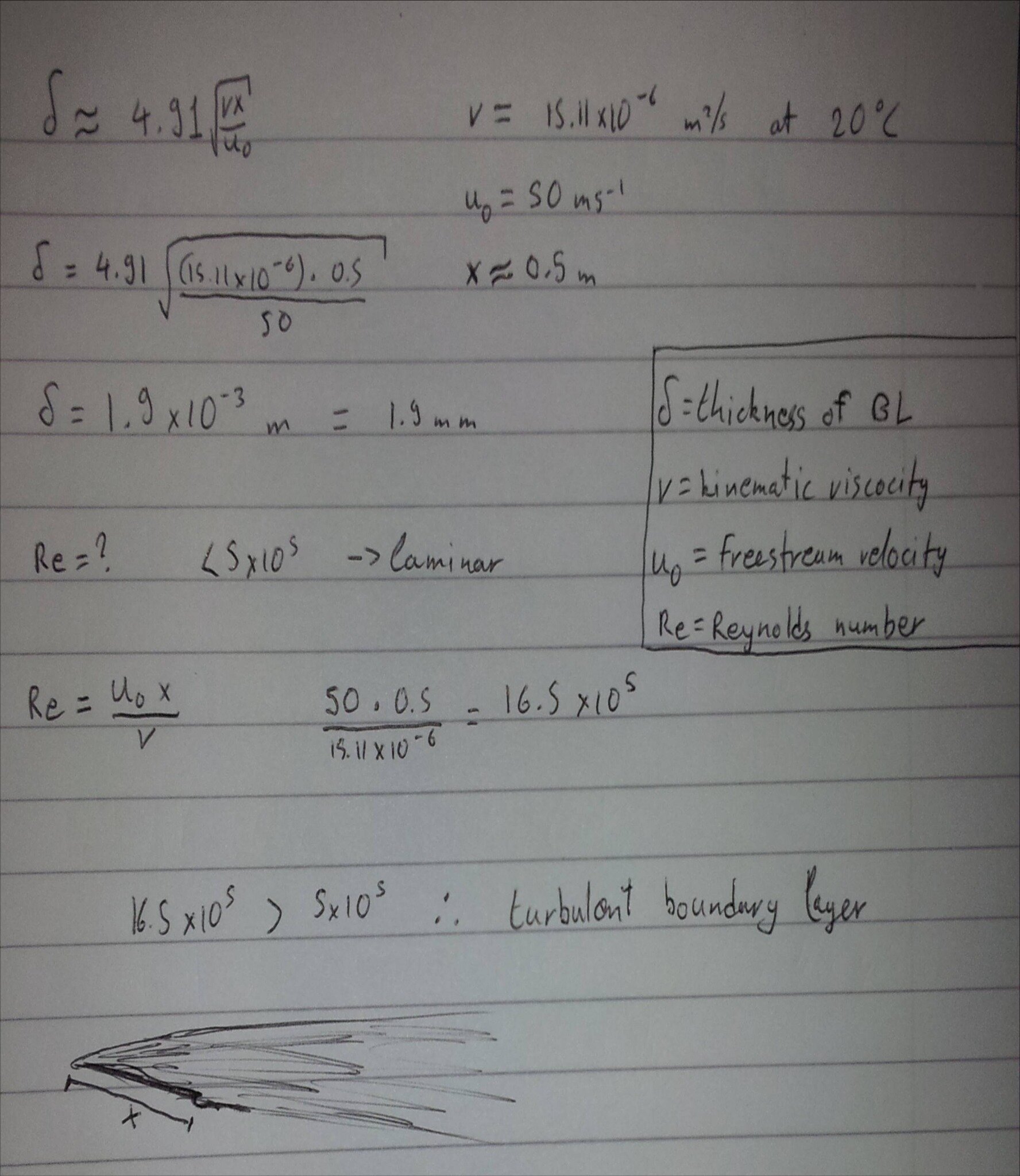
Simple calculation to give for the thickness of the boundary layer in front of the nose hole:

Image

The value i got was 1.9 mm which is probably not accurate enough but it gives you an idea..the hole in the nose is clearly much taller than 1.9mm so it is not there solely for cleaning up the boundary layer...it is probably there for cooling as well and we will find out if there is any other reason for it.

User avatar
amouzouris
105
Joined: 14 Feb 2011, 20:21

Re: Ferrari F138

Post

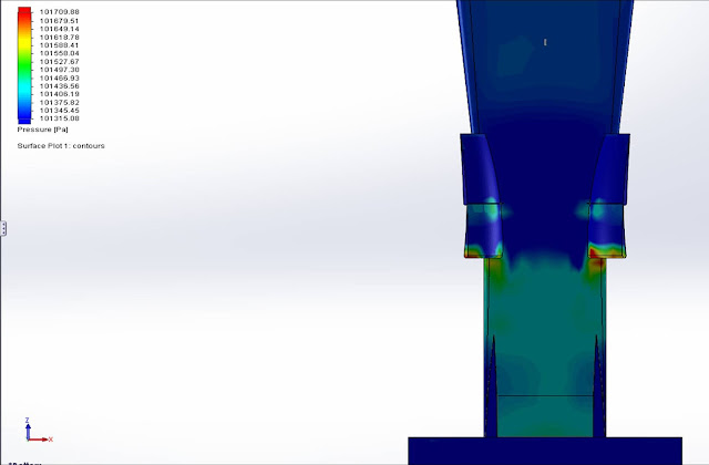
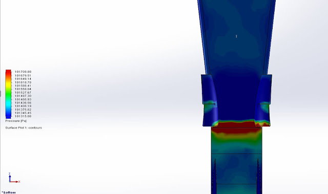
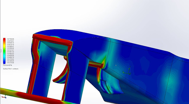
While I didn't find an adverse pressure gradient point in my CFD test...i omitted a feature of the nose which is the part close to the front bulkhead just behind the K in Kaspersky where the bodywork gets steeper which would probably produce an adverse gradient point...
However the hole is located exactly where the pressure decreases

Image

Image

Image

R_Redding
R_Redding
54
Joined: 30 Nov 2011, 14:22

Re: Ferrari F138

Post

What are the perforated sections in the splitters bow for ?...

In this photo by bhallg2k http://i.imgur.com/GvHHG82.jpg looking straight on into the splitter region ..it looks as if the bow has perforated sections on either side .
Could the duct/whole be passing air to this perforated region to create a drag reducing bondary layer on the splitter bow..or maybe reduce a boundary layer that builds up there.

It looks deliberate ,it doesn't look like a CF layup pattern. The RB9 has a similar section on its bow aswell.
Rob

bhall
bhall
244
Joined: 28 Feb 2006, 21:26

Re: Ferrari F138

Post

amouzouris wrote:While I didn't find an adverse pressure gradient point in my CFD test...i omitted a feature of the nose which is the part close to the front bulkhead just behind the K in Kaspersky where the bodywork gets steeper which would probably produce an adverse gradient point...
However the hole is located exactly where the pressure decreases
You've also omitted the rest of the car. I don't think you can test a component in isolation and expect the test to yield representative results, yanno? Wheel wake and downstream flow are just two of the many, many factors that determine how the front wing interacts with oncoming flow.

This piece from McCabism details how Red Bull's rear-wing DDRS last year helped to "pull" flow over the front wing.

Image

This piece discusses the Trefftz plane, which is behind an object, and the induced drag it creates on the object.

Image

The only real question I have at this point is, where on the F138 is the "peeled" flow vented? It's gotta go somewhere.
Last edited by bhall on 14 Feb 2013, 18:51, edited 2 times in total.

User avatar
amouzouris
105
Joined: 14 Feb 2011, 20:21

Re: Ferrari F138

Post

I do not disagree with you...but testing the whole car would 1st of all be too time consuming and also it would be the difference between an adverse pressure gradient forming and not...of course the point where the pressure decreases which I found to be exactly where the whole is might be shifted further to the front or back if i tested a whole car...

I know how flow over the front wing affects the rear of the car and vice versa...I have a similar blogpost on the RedBull and its DDRS in my blog as well

I carried out the test to get an idea of where the pressure changes and i found it very interesting that it was exactly where the nose hole is located...that is the reason i posted it here

bhall
bhall
244
Joined: 28 Feb 2006, 21:26

Re: Ferrari F138

Post

On second thought, why shouldn't the inlet be placed where pressure is decreased? It doesn't make much sense to try to prevent flow separation after the flow has separated. That would be like putting on a condom after sex.

User avatar
amouzouris
105
Joined: 14 Feb 2011, 20:21

Re: Ferrari F138

Post

bhallg2k wrote:On second thought, why shouldn't the inlet be placed where pressure is decreased? It doesn't make much sense to try to prevent flow separation after the flow has separated. That would be like putting on a condom after sex.
That is another thought I had, which might also explain why the hole is so tall...If they wanted to just peel off the boundary layer a much shorter hole would have done the job

bhall
bhall
244
Joined: 28 Feb 2006, 21:26

Re: Ferrari F138

Post

amouzouris wrote:That is another thought I had, which might also explain why the hole is so tall...If they wanted to just peel off the boundary layer a much shorter hole would have done the job
I probably should have said the inlet reduces mass flow to counter the increase in pressure caused by an adverse pressure gradient. I think that's more illustrative of what's really going on.

Either way, I think the inlet has to be large enough to work at all speeds without choking, and it has to be small enough to avoid drawing in too much air.

EDIT: Incidentally, you did find an adverse pressure gradient. ;)

Image
R_Redding wrote:What are the perforated sections in the splitters bow for ?...

[...]
That could be where the system vents. Small ducts oriented in the direction of flow could perhaps energize said flow. (If so, I'm really starting to love the multi-faceted elegance of this system.)

But, then I wonder if those ducts could vent fast enough to keep the system itself from choking.
Last edited by bhall on 14 Feb 2013, 20:03, edited 1 time in total.

User avatar
Redragon
19
Joined: 24 May 2011, 12:23

Re: Ferrari F138

Post

With so much technical stuff discussed that goes beyond my knowledge. I am enjoying it don't get me wrong.
I wanted to bring an observation in terms of air flow.
The shape of lotus on the under nose area has been always got my attention as it is not straight, it is in a shape of "U"
And reading all you, it have brought to my mind again that strange shape, why that "u"?
Maybe Ferrari are creating that kind of "u" with the hole. Which I am sure is benefiting with the flow but the whole obviously has other proporses too.

bhall
bhall
244
Joined: 28 Feb 2006, 21:26

Re: Ferrari F138

Post

I think the bulbous underside of the Lotus nose reduces static pressure, meaning it has the same effect as the pylons on the Ferrari. The difference is that it does so by making the nose a veritable wing whereas the pylons on the F138 form a Venturi.

Someone brighter than me will have to tell you exactly if/why one method is better than the other. But, I think the Lotus solution sacrifices mass flow.

User avatar
amouzouris
105
Joined: 14 Feb 2011, 20:21

Re: Ferrari F138

Post

bhallg2k wrote:
EDIT: Incidentally, you did find an adverse pressure gradient. ;)
Thats actually the lip of the hole!

bhall
bhall
244
Joined: 28 Feb 2006, 21:26

Re: Ferrari F138

Post

...and? That's going to show up no matter what's there as long as something is there.

User avatar
Chuckjr
38
Joined: 24 Feb 2012, 08:34
Location: USA

Re: Ferrari F138

Post

I think that question should be posed in the Lotus thread? Just a thought.

In the bit of research you all have done...which seems to conclude the hole is located in an area where the pressure is already decreasing...could it be that the hole acts as a sort of vacuum like apparatus which helps to pull even more air volume into this lower pressure area? Would this not only improve efficiency and use of the space, but also to increase speed of the air passing down into the bottom of the car and eventual diffuser? It seems Ferrari is trying to get as much air mass feeding the front of the car (for use at the back of the car) that this theory would compliment their design intent?

If this consideration was already posed, my apologies. I don't mean to be a parrot.
Watching F1 since 1986.

User avatar
amouzouris
105
Joined: 14 Feb 2011, 20:21

Re: Ferrari F138

Post

bhallg2k wrote:...and? That's going to show up no matter what's there as long as something is there.
Oh I thought you didn't notice that the second pic was with the hole!

bhall
bhall
244
Joined: 28 Feb 2006, 21:26

Re: Ferrari F138

Post

We're effectively on the same page. (Don't let my lack of social grace discourage you.)
Chuckjr wrote:[...]

In the bit of research you all have done...which seems to conclude the hole is located in an area where the pressure is already decreasing...could it be that the hole acts as a sort of vacuum like apparatus which helps to pull even more air volume into this lower pressure area?
[...]
I think it's placed in an area where pressure has already been decreased by the Venturi. The inlet then collects air flow at a point just before the area where pressure would normally begin to increase if the inlet was not there to reduce volume to counter that pressure increase. The inlet will have to have negative pressure else it will collect nothing, but I don't think it's the principle mechanism by which pressure is reduced.

Of course, this is all predicated on the notion that the effects I've described are the system's intended purpose. It's also reliant on a vent that can release pressure within the system at a rate high enough to keep it from choking. I don't know where that vent is, though. But, I really like the idea that it's on the splitter as a series of small vents that release pressure and simultaneously energize flow around the splitter/sidepods.
Last edited by bhall on 14 Feb 2013, 23:04, edited 1 time in total.