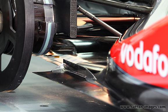
Diffuser functions

Here are our CFD links and discussions about aerodynamics, suspension, driver safety and tyres. Please stick to F1 on this forum.
shelly
shelly
136
Joined: 05 May 2009, 12:18

Re: Diffuser functions

Post

Raptor22 wrote:Jeepers all this discussion on a topic thats covered under theormodynamics 101.

Diffusors work better without sudden changes in direction. Its function is too raise pressure and reduce velocity without shock.
Without Shock is important since shock waves ina diffusor increase the onset of choking.
Again 'm with Marekk on this one.
Diffusor kink lines?!! Who makes these things up? Diffusors have to be joined to the floor somehow and typically its at a dfined edge where floor and diffusor meet. the larger the radius the less the opportunity for shock waves to develop, the less the chance of diffusor choking the less senistive the car is to underbody airflow changes.

Its just a diffusor, its not a trilithim warp generator. there no science fiction involved.

raptor22, I think you are getting confused, and in that you make mistakes.
Diffusers are connected to flat floor with a radius, but that radius is small; it is more similar to the photograph posted by marekk than to the cad image. Webber flip up of last year could give some evidence.
I think there is also a rule limiting that radius, and ferrari found a loophole around that since 2001.

Advice: do not be so aggressive when you write sentences that could prove wrong, as you did in your post.
twitter: @armchair_aero

marekk
marekk
2
Joined: 12 Feb 2011, 00:29

Re: Diffuser functions

Post

horse wrote:
Raptor22 wrote:in a subsonic diffusor its the boundary layer separation we want to avoid. We still term the sudden reduction in velocity "Shock". We are not refering to shockwaves such as in a supersonic nozzle/diffusor.
Must be a semantic nightmare for those working on transonic flows.
Not really. "shock" wave means just very abrupt, almost discontinuous change in medium properties (pressure, temp, density). One state - bum - next state.

Raptor22 described it exactly: we need all of the diff surface we got to extract maximum efficiency from it. If boundary layer detaches from surfaces, this area is not working at all, additionally we have back flow and vortexes start to form, which means drag.

As all things in real world, and in fluids even more so, it's highly dynamic process:
Image

marekk
marekk
2
Joined: 12 Feb 2011, 00:29

Re: Diffuser functions

Post

shelly wrote:
Raptor22 wrote:Jeepers all this discussion on a topic thats covered under theormodynamics 101.

Diffusors work better without sudden changes in direction. Its function is too raise pressure and reduce velocity without shock.
Without Shock is important since shock waves ina diffusor increase the onset of choking.
Again 'm with Marekk on this one.
Diffusor kink lines?!! Who makes these things up? Diffusors have to be joined to the floor somehow and typically its at a dfined edge where floor and diffusor meet. the larger the radius the less the opportunity for shock waves to develop, the less the chance of diffusor choking the less senistive the car is to underbody airflow changes.

Its just a diffusor, its not a trilithim warp generator. there no science fiction involved.

raptor22, I think you are getting confused, and in that you make mistakes.
Diffusers are connected to flat floor with a radius, but that radius is small; it is more similar to the photograph posted by marekk than to the cad image. Webber flip up of last year could give some evidence.
I think there is also a rule limiting that radius, and ferrari found a loophole around that since 2001.

Advice: do not be so aggressive when you write sentences that could prove wrong, as you did in your post.

Looked at 2011 diffusers and you are right, shelly.
There is distinct kink in all cars and the shape is more like this on the photo.

No more radius limits AFAIK, only this rule:
3.12.7 No bodywork which is visible from beneath the car and which lies between the rear wheel centre line and a
point 350mm rearward of it may be more than 125mm above the reference plane. With the exception of the
aperture described below, any intersection of the surfaces in this area with a lateral or longitudinal vertical
plane should form one continuous line which is visible from beneath the car.
An aperture for the purpose of allowing access for the device referred to in Article 5.16 is permitted in this
surface. However, no such aperture may have an area greater than 3500mm2 when projected onto the
surface itself and no point on the aperture may be more than 100mm from any other point on the aperture.
Additionally, any bodywork in this area must produce uniform, solid, hard, continuous, rigid (no degree of
freedom in relation to the body/chassis unit), impervious surfaces under all circumstances

User avatar
horse
6
Joined: 23 Oct 2009, 17:53
Location: Bilbao, ES

Re: Diffuser functions

Post

The fluid flow in a diffuser in ground effect represents a complex fluid dynamic problem with features such as flow separation, vortex flow, and flow reversal.
The Force and Pressure of a Diffuser-Equipped Bluff Body in Ground Effect
Andrea E. Senior and Xin Zhang
Journal of Fluids Engineering MARCH 2001, Vol. 123
"Words are for meaning: when you've got the meaning, you can forget the words." - Chuang Tzu

shelly
shelly
136
Joined: 05 May 2009, 12:18

Re: Diffuser functions

Post

@marekk: I am happy that you have checked again. Think that raptor22 has something to learn from you.

About radial-vertical pressure gradient: think about streamlines flowing parallel at the end of the flat floor in the 2d image or the 2d video you posted.
They have to make a curve around the kink. The uppermost in you image does not have to: it stays parallel to the ground (which is on top in your image); the others have to make a curve whose radius is decreasing with reducing ditance from the kink.
It is pressure being lower at the kink that makes streamlines go around the curved path; tighterstreamlinecurve means more intense radial pressure gradient.

Until stall of course.
twitter: @armchair_aero

volarchico
volarchico
0
Joined: 26 Feb 2010, 07:27

Re: Diffuser functions

Post

horse wrote:The Force and Pressure of a Diffuser-Equipped Bluff Body in Ground Effect
Andrea E. Senior and Xin Zhang
Journal of Fluids Engineering MARCH 2001, Vol. 123
You wouldn't happen to have a pdf version? I did a search and couldn't find one online (well, for free).

volarchico
volarchico
0
Joined: 26 Feb 2010, 07:27

Re: Diffuser functions

Post

And there's a good description of diffusers in "The Aerodynamics of Race Cars" starting on page 19.

http://strangeholiday.com/oops/stuff/an ... 092016.pdf

marekk
marekk
2
Joined: 12 Feb 2011, 00:29

Re: Diffuser functions

Post

shelly wrote:@marekk:
About radial-vertical pressure gradient: think about streamlines flowing parallel at the end of the flat floor in the 2d image or the 2d video you posted.
They have to make a curve around the kink. The uppermost in you image does not have to: it stays parallel to the ground (which is on top in your image); the others have to make a curve whose radius is decreasing with reducing ditance from the kink.
It is pressure being lower at the kink that makes streamlines go around the curved path; tighterstreamlinecurve means more intense radial pressure gradient.

Until stall of course.
I'm still not convinced.
Flow lines just visualize paths of air molecules, but contain no information about speed of those molecules.

On the pictures, we can clearly see flow's speed decrease and static pressure increase along diff top wall from inlet to outlet.

Air molecules on separate flow lines don't have to arrive at diff exit at the same time.
Partial stall can occur on every point on diff surface and flow can even reattach later.
Of course stall at kink means all downforce from diff is lost.

shelly
shelly
136
Joined: 05 May 2009, 12:18

Re: Diffuser functions

Post

marekk wrote:
shelly wrote:@marekk:
About radial-vertical pressure gradient: think about streamlines flowing parallel at the end of the flat floor in the 2d image or the 2d video you posted.
They have to make a curve around the kink. The uppermost in you image does not have to: it stays parallel to the ground (which is on top in your image); the others have to make a curve whose radius is decreasing with reducing ditance from the kink.
It is pressure being lower at the kink that makes streamlines go around the curved path; tighterstreamlinecurve means more intense radial pressure gradient.

Until stall of course.
I'm still not convinced.
Flow lines just visualize paths of air molecules, but contain no information about speed of those molecules.

On the pictures, we can clearly see flow's speed decrease and static pressure increase along diff top wall from inlet to outlet.

Air molecules on separate flow lines don't have to arrive at diff exit at the same time.
Partial stall can occur on every point on diff surface and flow can even reattach later.
Of course stall at kink means all downforce from diff is lost.
I the viedo and images you posted we see big stalls. What I m sying is this: whe a difuser is working and streamline changedirection, there has to be a pressure gradient which makes this change in direction happen
twitter: @armchair_aero

User avatar
ringo
230
Joined: 29 Mar 2009, 10:57

Re: Diffuser functions

Post

why the use of the word stall? Stall is something very relative.
why not separation and eddy formation?

The diffuser regs are very restrictive this year and all teams will use the max height allowed. The most they can do differently is to change the profile curve.
Rake is not an issue as it make the direction change easier.

A concave curve seems to be the curve of choice this year, and that
's very prone to separation. So there could be more to it than a 2 dimensional flow plot.
I think that could be worth discussing.
For Sure!!

shelly
shelly
136
Joined: 05 May 2009, 12:18

Re: Diffuser functions

Post

@ringo: I think
-stall-separation could be taken as synoinims in this context
- I do not understand why you say rake is not an issue - I do not remember who said it was an issue and why. I think that rea ride height could be imposrtannt as it inflences the exapnsion ratio in the diffuser
-agree with you that diffusers are highly 3dimensional, but we have first to see simpler things in 2d and then intorduce 3d effects, fences, vortices etc

We have yet to find agreement on kink line suction peak for example
twitter: @armchair_aero

marekk
marekk
2
Joined: 12 Feb 2011, 00:29

Re: Diffuser functions

Post

shelly wrote:
marekk wrote:
shelly wrote:@marekk:
About radial-vertical pressure gradient: think about streamlines flowing parallel at the end of the flat floor in the 2d image or the 2d video you posted.
They have to make a curve around the kink. The uppermost in you image does not have to: it stays parallel to the ground (which is on top in your image); the others have to make a curve whose radius is decreasing with reducing ditance from the kink.
It is pressure being lower at the kink that makes streamlines go around the curved path; tighterstreamlinecurve means more intense radial pressure gradient.

Until stall of course.
I'm still not convinced.
Flow lines just visualize paths of air molecules, but contain no information about speed of those molecules.

On the pictures, we can clearly see flow's speed decrease and static pressure increase along diff top wall from inlet to outlet.

Air molecules on separate flow lines don't have to arrive at diff exit at the same time.
Partial stall can occur on every point on diff surface and flow can even reattach later.
Of course stall at kink means all downforce from diff is lost.
I the viedo and images you posted we see big stalls. What I m sying is this: whe a difuser is working and streamline changedirection, there has to be a pressure gradient which makes this change in direction happen
We are talking about (non)existent acceleration of flow around diff kink.
To accelerate and change momentum of flow upwards you need some force - upward facing negative gradient (high to low) of pressure. Our gradient is opposite.

Flow lines in those pictures separate simply due to expansion.

Thanks to Renault for today's free open world wind tunnel visualization of real F1 car flows:

Image

Looking at the sparks, we can clearly see: (almost) no flow direction change in vertical plane from diff.


On this one can see horizontal jet of smoke form diff and upfwards facing flows form beam and rear wings:

Image

shelly
shelly
136
Joined: 05 May 2009, 12:18

Re: Diffuser functions

Post

@marekk:
- sparks in r31 picture catch an instant , we would have to see the video; also remeber thatlower streamlines near the ground are the least deflected
-the acceleration we are talking about is the existent centripetal acceleration needed to turn streamlines up in the car (would be down in your 2d pictures) So on the body it acts from up to down on a car (downforce from suction peak) and would act from down to up in your 2d pictures/videos.
Maybe the images being oriented opposite form a car diffuser has caused misunderstanding on the direction of the force.
twitter: @armchair_aero

User avatar
ringo
230
Joined: 29 Mar 2009, 10:57

Re: Diffuser functions

Post

Image

concave diffuser. look right under lower wishbone.
For Sure!!

User avatar
PlatinumZealot
559
Joined: 12 Jun 2008, 03:45

Re: Diffuser functions

Post

Let us all get this straight.

1. Diffusers do not impart work. (unless you have a moving diffuser :roll: )
2. the purpose of the diffuser is to allow the fluid to leave the floor with minimal flow losses.

Everybody can see that? OK..

Now what else about diffuser functionality is there that would make a good discussion...
🖐️✌️☝️👀👌✍️🐎🏆🙏

Racing Green in 2028