2014 Design

Here are our CFD links and discussions about aerodynamics, suspension, driver safety and tyres. Please stick to F1 on this forum.
F1PuertoRico
F1PuertoRico
0
Joined: 24 Aug 2011, 02:46

Re: 2014 Design

Post


Mitsuro Sano
Mitsuro Sano
11
Joined: 13 Dec 2013, 20:59

Re: 2014 Design

Post

Hello,
I've been a long-time follower of F1technical but this is my first post here so it's an opportunity to me to tell you how good this place is! :)
I've been doing cars before for the Grand Prix 4 game and I've tried to do a car based to the 2014 regulations :
Image

I was about to ask if such nose would be legal and efficient but seeing Scarbs sketching this means that it may not a bad idea! What would be the advantage/disadvantage of this kind of nose over the Blanchimont-type nose?

Huntresa
Huntresa
54
Joined: 03 Dec 2011, 11:33

Re: 2014 Design

Post

Mitsuro Sano wrote:Hello,
I've been a long-time follower of F1technical but this is my first post here so it's an opportunity to me to tell you how good this place is! :)
I've been doing cars before for the Grand Prix 4 game and I've tried to do a car based to the 2014 regulations :
http://s536.photobucket.com/user/Mitsur ... d.jpg.html

I was about to ask if such nose would be legal and efficient but seeing Scarbs sketching this means that it may not a bad idea! What would be the advantage/disadvantage of this kind of nose over the Blanchimont-type nose?
If anything that nose could create to much front downforce unless the air coming of the plough can be used properly at the back to gain better rear downforce.

radosav
radosav
23
Joined: 05 Feb 2012, 20:46

Re: 2014 Design

Post

Mitsuro Sano wrote:Hello,
I've been a long-time follower of F1technical but this is my first post here so it's an opportunity to me to tell you how good this place is! :)
I've been doing cars before for the Grand Prix 4 game and I've tried to do a car based to the 2014 regulations :
http://s536.photobucket.com/user/Mitsur ... d.jpg.html

I was about to ask if such nose would be legal and efficient but seeing Scarbs sketching this means that it may not a bad idea! What would be the advantage/disadvantage of this kind of nose over the Blanchimont-type nose?
Do you mean GEOFF CRAMMOND'S GRAND PRIX 4 ?

User avatar
ringo
230
Joined: 29 Mar 2009, 10:57

Re: 2014 Design

Post

Keep in mind this rule:

15.4.3 An impact absorbing structure must be fitted in front of the survival cell. This structure need
not be an integral part of the survival cell but must be solidly attached to it.
No part of this structure may lie more than 525mm above the reference plane.
It must have a single external cross section, in horizontal projection, of more than 9000mm² at
a point 50mm behind its forward-most point. Furthermore :
a) No part of this cross-section may lie more than 250mm or less than 135mm above the
reference plane.
b) The centre of area of this section must be no more than 185mm above the reference
plane and no less than 750mm forward of the front wheel centre line.

I think the part highlighted in part b, may put some of the noses drawn here in contravention. I haven't checked those noses obviously, but just saying this part has a big influence on the overall shape when viewed from a horizontal projection.
For the center of area to be no less than 750mm forward of the front wheel center line, then that means that half the area or more must be at this line or ahead of it; correct me if i'm wrong. I'm assuming a horizontal projection is on a vertical plane.
For Sure!!

Sevach
Sevach
1081
Joined: 07 Jun 2012, 17:00

Re: 2014 Design

Post

Giando wrote:
Nice one, who's the author?
MCDesign, i don't know the real name of the guy behind it.


About the plough nose, if it complies to the rules i think it's a winner.

bonjon1979
bonjon1979
30
Joined: 11 Feb 2009, 17:16

Re: 2014 Design

Post

scarbs wrote:look to the left....
Nah, I don't see it. Take your word for it.

User avatar
aleks_ader
90
Joined: 28 Jul 2011, 08:40

Re: 2014 Design

Post

Sevach wrote:
Giando wrote:
Nice one, who's the author?
About the plough nose, if it complies to the rules i think it's a winner.
Why not? If lower "snow plough" lip is structural (crash structure). And if upper lip is vanity or modesty panel it is plusibble. Just teams need to make compromise and maybe add some weight due vanity or even more drastically lowered or shortened upper lip in that extend that vanity panel will became much smaller. Mclaren did some pretty decent snow plought designs but as a aerodynamics you REALLY need good understanding of CFD, windtunnel and all correlation fer best track performance.

I expect that smaller teams or many other teams will go Caterham so known blanchimond nose whitch looks "ugly", but it is much more practical choice to go. Like many users on that topic conclude or share same opinion it is much more cleverness to go same winning philosophy-->hight nose-->more air toward splitter-->try to effectively seal or feed diffuozor sidewalls or coke bottle-->generete more rear DF--<balance that and you gota blistering car capable of... Firtly engineers throw year gathered tons of usefull CFD, track, windtunnel data and you gotta had very big b*** to almost throw all that throw window and (except Mclaren) go completely from scratch.

So that step it is unrecommended for smaller teams because it could easily very get wrong and they cannot afford to much gamble. Maybe Mclaren is capable or Mercedes, but hell who knows...
"And if you no longer go for a gap that exists, you're no longer a racing driver..." Ayrton Senna

User avatar
SectorOne
166
Joined: 26 May 2013, 09:51

Re: 2014 Design

Post

Image

Now this one is ugly.
"If the only thing keeping a person decent is the expectation of divine reward, then brother that person is a piece of sh*t"

User avatar
lio007
319
Joined: 28 Jan 2013, 23:03
Location: Austria

Re: 2014 Design

Post

There is one question that came into my mind.
In terms of blown diffusers: are there any other possibilities or smart design solutions to get some“ strong flows of air“ to seal the diffuser?

Wild thoughts:
To make an additional intake at the beginning of the sidepods behind the bargeboards, then make a duct through the whole sidepods , accelerate the air in this duct (I really don’t know if this acceleration is possible, if you get enough air or how you can achieve that). Finally the outtake of this duct is similar to the exhaust exit from the 2011-blown-diffusers.

Or: To make additional exits on the turbocharger. This outtakes don’t exit exhaust gases but „normal air“. This „turbocharged air“ is ducted to similar exhaust-exit positions from the 2011-blown-diffusers. I really don’t know if you can feed the turbocharger with two types of gases an handle them seperated.

To be honest, I’m no aerodynamicist as no engine-specialist. So this are only some ideas without any special thechnical background.

User avatar
aleks_ader
90
Joined: 28 Jul 2011, 08:40

Re: 2014 Design

Post

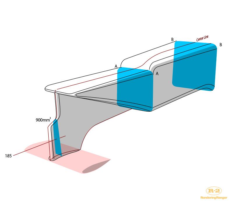
There is also in play mandated COfG of front 90 000 mm^2 crossection. Dont forget that!
Fia_Tech_2014_regs wrote:It must have a single external cross section, in horizontal projection, of more than 9000mm² at a point 50mm behind its forward-most point. Furthermore :
a) No part of this cross-section may lie more than 250mm or less than 135mm above the reference plane.
b) The centre of area of this section must be no more than 185mm above the reference plane and no less than 750mm forward of the front wheel centre line.
So i think all pictures should take that also in account...
lio007 wrote:There is one question that came into my mind.
In terms of blown diffusers: are there any other possibilities or smart design solutions to get some“ strong flows of air“ to seal the diffuser?

Wild thoughts:
To make an additional intake at the beginning of the sidepods behind the bargeboards, then make a duct through the whole sidepods , accelerate the air in this duct (I really don’t know if this acceleration is possible, if you get enough air or how you can achieve that). Finally the outtake of this duct is similar to the exhaust exit from the 2011-blown-diffusers.
Nope to low energy and also to much drag for really no gain. Remember Ferrari had just that kind of problems with acer ducts in 2012.
Or: To make additional exits on the turbocharger. This outtakes don’t exit exhaust gases but „normal air“. This „turbocharged air“ is ducted to similar exhaust-exit positions from the 2011-blown-diffusers. I really don’t know if you can feed the turbocharger with two types of gases an handle them seperated.

To be honest, I’m no aerodynamicist as no engine-specialist. So this are only some ideas without any special thechnical background.
No! Rules are very strict here all fluids which enter turbo must also exit on the exhaust tailppipe... Look F1 turbo engine thread and there we all agree that there only possibility to instal ERG. Sadly nothing elso you can do with exhaoust unless just couple monkey farts ( :D )...
"And if you no longer go for a gap that exists, you're no longer a racing driver..." Ayrton Senna

eyalynf1
eyalynf1
6
Joined: 24 May 2011, 01:05

Re: 2014 Design

Post

ringo wrote:Keep in mind this rule:

15.4.3 An impact absorbing structure must be fitted in front of the survival cell. This structure need
not be an integral part of the survival cell but must be solidly attached to it.
No part of this structure may lie more than 525mm above the reference plane.
It must have a single external cross section, in horizontal projection, of more than 9000mm² at
a point 50mm behind its forward-most point. Furthermore :
a) No part of this cross-section may lie more than 250mm or less than 135mm above the
reference plane.
b) The centre of area of this section must be no more than 185mm above the reference
plane and no less than 750mm forward of the front wheel centre line.

I think the part highlighted in part b, may put some of the noses drawn here in contravention. I haven't checked those noses obviously, but just saying this part has a big influence on the overall shape when viewed from a horizontal projection.
For the center of area to be no less than 750mm forward of the front wheel center line, then that means that half the area or more must be at this line or ahead of it; correct me if i'm wrong. I'm assuming a horizontal projection is on a vertical plane.
Part b is too vague. Do they intend "center" as in average of upper and lower z coordinates, or do they mean the centroid, as in the arithmetic mean of all y-coordinates in the cross-sectional area? Not the same thing!

User avatar
ringo
230
Joined: 29 Mar 2009, 10:57

Re: 2014 Design

Post

Image

What rule is that 900mm2 area referring to?

It can't be what i quoted from the regs, as it would not be over 135mm and be 9000 not 900.
I myself have been confused, but i now see why i read it incorrectly.

What the rule also does is limit the length of the nose. The nose tip can be no further than 800mm from front wheel center line.

part b is referring to the centroid.
For Sure!!

wesley123
wesley123
204
Joined: 23 Feb 2008, 17:55

Re: 2014 Design

Post

ringo wrote: What the rule also does is limit the length of the nose. The nose tip can be no further than 800mm from front wheel center line.
Aslight switch in discussion here. But wouldn't such a rule make it benificial to bring the front wheel centerline as far forward as possible? This in turn could create a longer(and thus less wide) nose cone.
"Bite my shiny metal ass" - Bender

User avatar
variante
138
Joined: 09 Apr 2012, 11:36
Location: Monza

Re: 2014 Design

Post

ringo wrote:The nose tip can be no further than 800mm from front wheel center line.
NO LESS than 800mm forward of the front wheel centre line.
Is that thin pylon supposed to be the crash structure?? The driver would be condemned...
Edit: it's unrealistic from another point of view: the thinner the section, the greater the distance between the centroid and the lowest point of bodywork allowed; this distance, however, can't be greater than 50mm by regulations, so the actual section would never be "thin".