Hello Tok-Tokkie.
You write:
“Four stroke boxer engines have a double throw crank so both pistons reach TDC simultaneously thereby balancing their rocking couple. You cross radial does the converse. You have balancing software but I must say I remain sceptical.”
A boxer is not so good, as explained below.
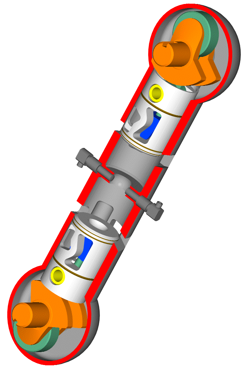
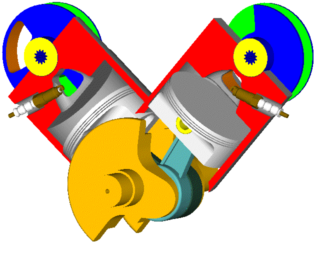
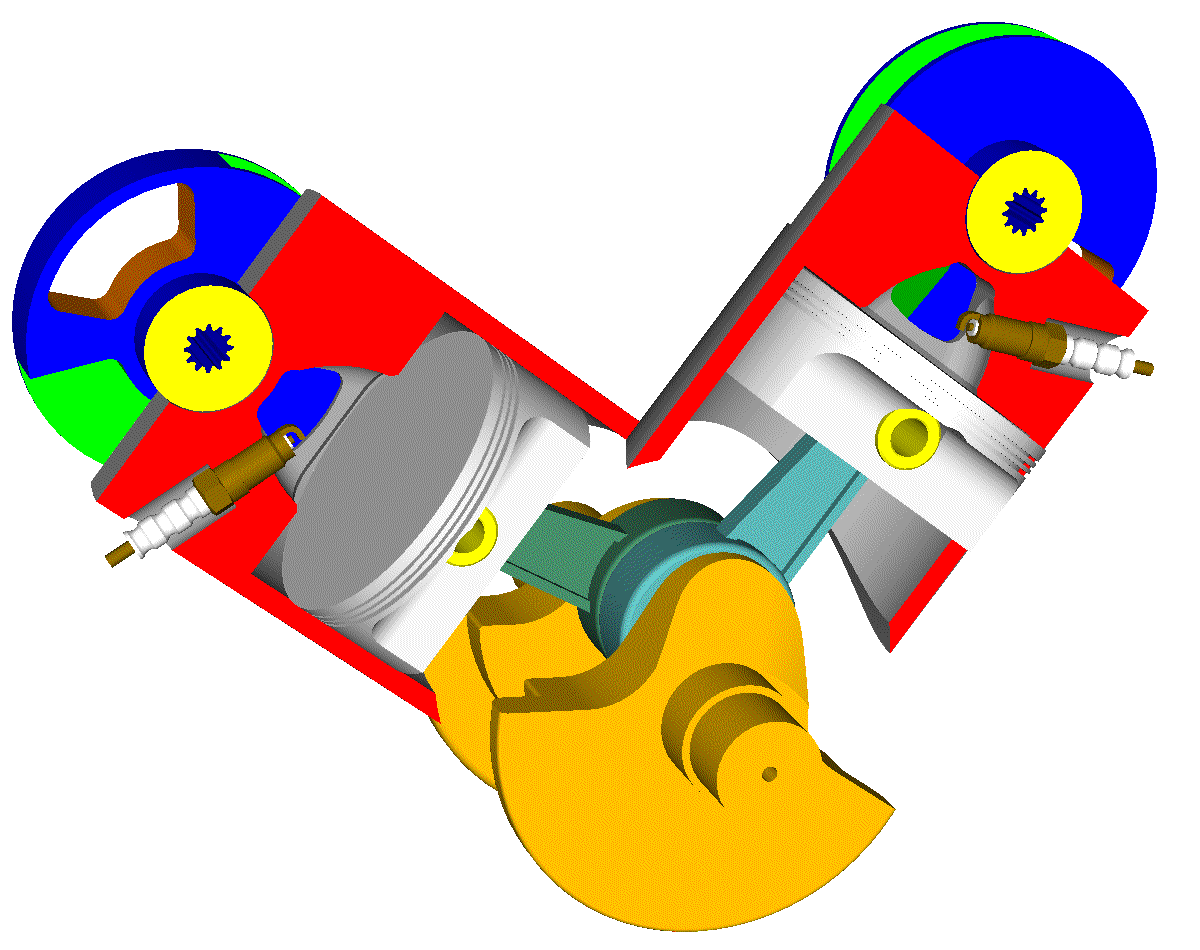
In a conventional boxer (say, BMW R1200GS motorcycle) the two cylinder axes are at a substantial offset from each other:

In the following drawing the cylinder offset is more obvious:
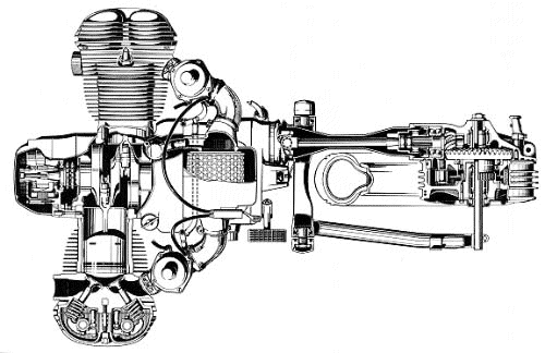
With a, say, 25mm wide web between the two crankpins and with a 20mm wide connecting rod big-end, the overall offset between the two cylinder axes is: 25+2*(20/2)=45mm.
While the inertia force from the one piston is equal and opposite to the inertia force from the other piston, these two forces are at a significant (say 45mm) offset. The result is zero total inertia force plus an unbalanced free inertia moment (or pair of forces). The balance webs on the crankshaft can cancel only a part of this inertia moment. The rest vibrates the engine.
With the two pistons stopping simultaneously at their TDC’s, and being simultaneously at their middle stroke, i.e. near their maximum speed, another kind of vibration results.
It is the inertia torque.
The set of crankshaft / flywheel has to accelerate when the two pistons are approaching their TDC’s (to absorb the kinetic energy of the pistons), and to decelerates when the two pistons are leaving their TDC’s (to provide the required kinetic energy to the pistons).
You can think of it by considering the inertia thrust forces acting on the cylinder liners due to the con-rod leaning, but the energy approach seems simpler. The inertia thrust forces on the two cylinder liners is a pair of forces (a torque, a moment) that tries to vibrate the casing about the crankshaft axis.
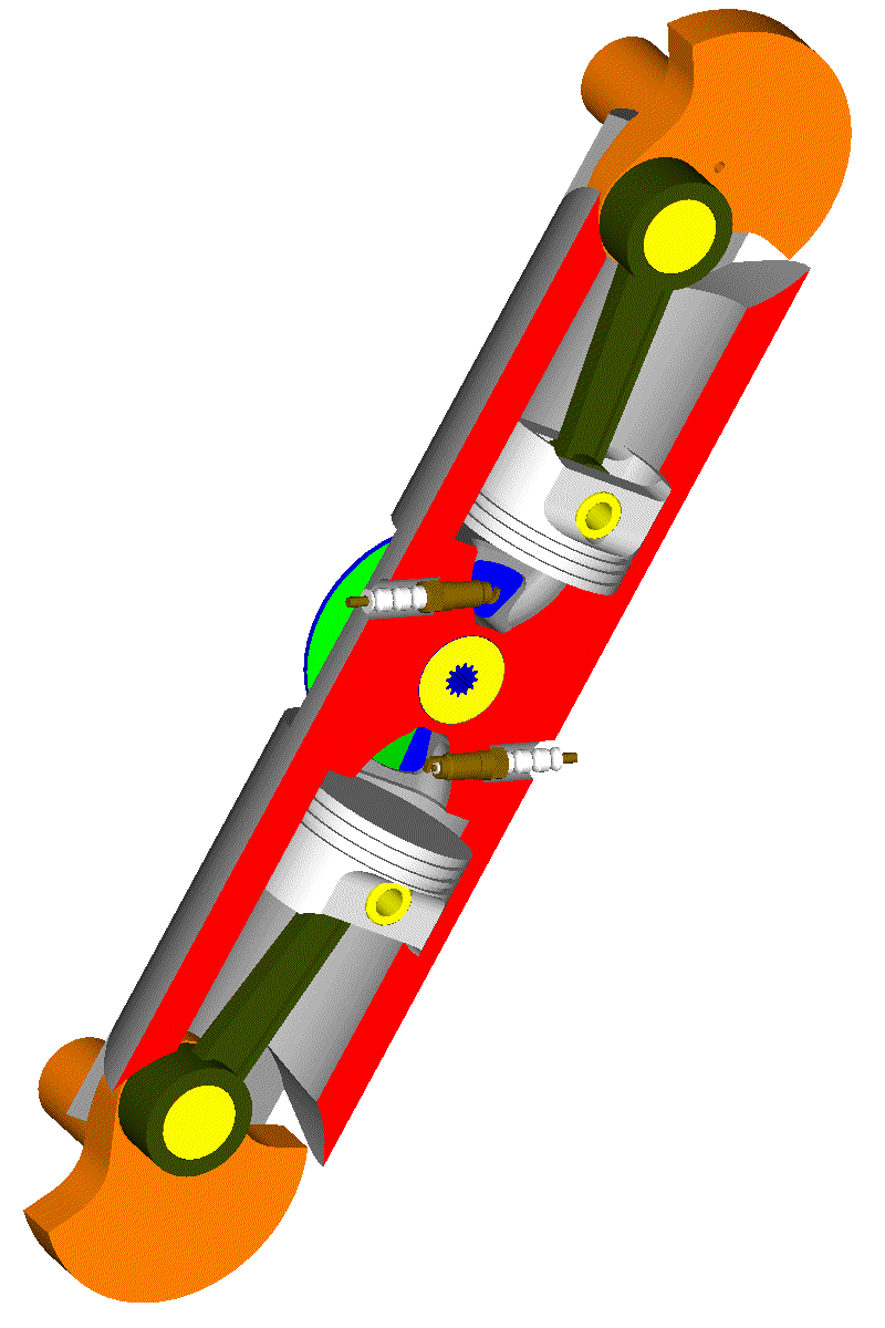
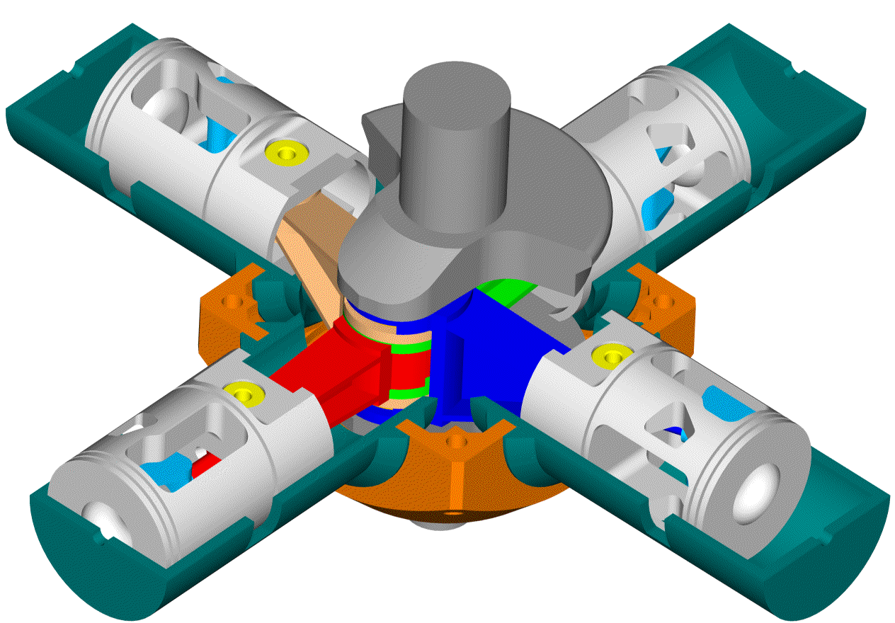
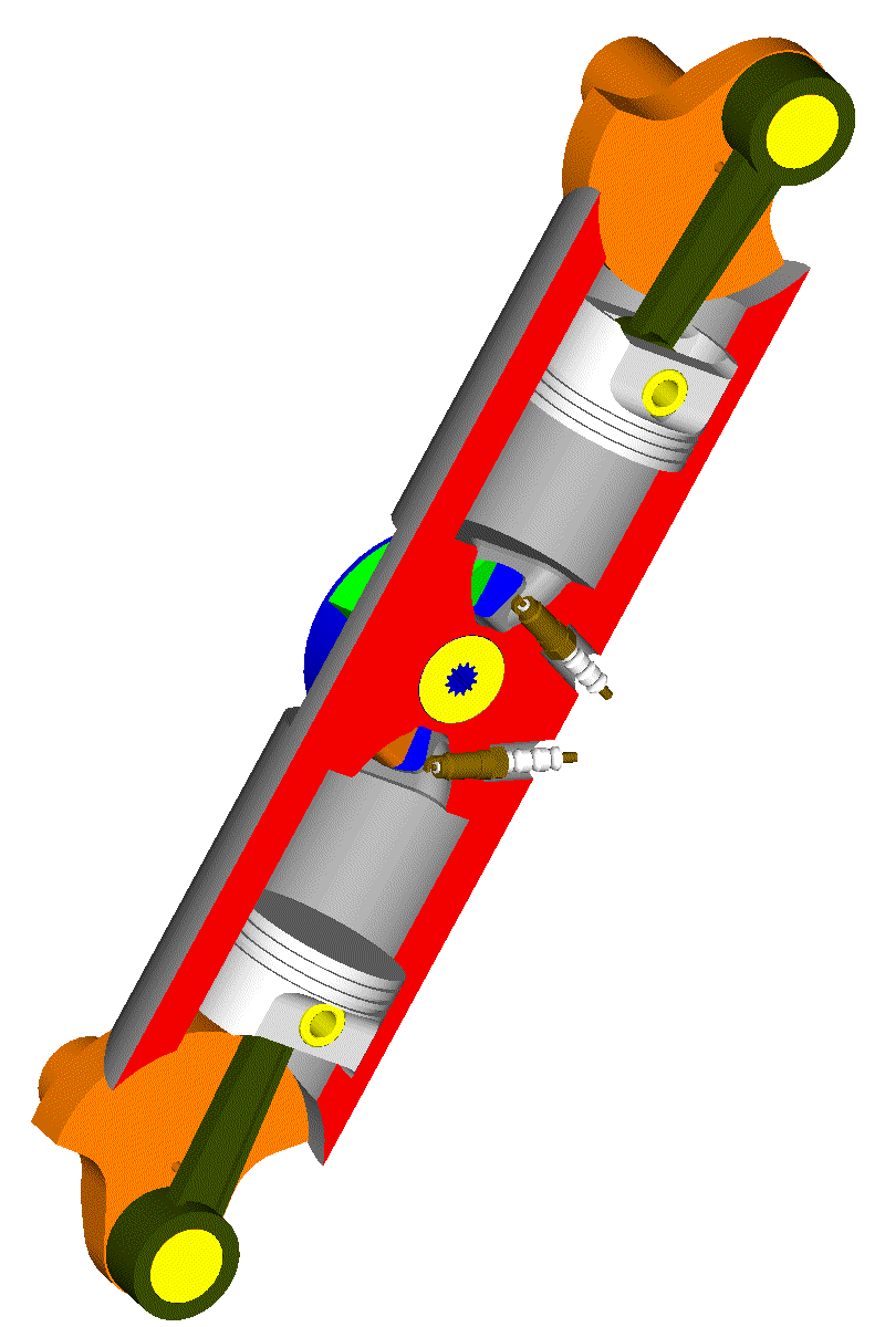
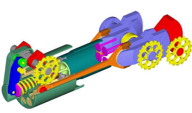
Take now the Cross-Radial PatAT engine:
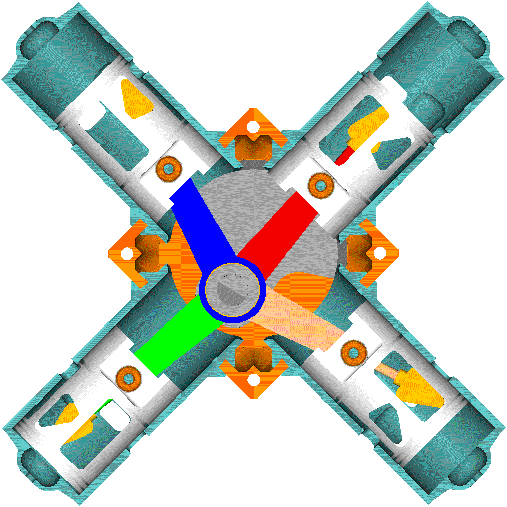
In this PatAT Cross Radial the combustion chambers are formed in the cylinder heads and not on the piston crowns (colder pistons).
All the cylinder axes are coplanar.
Let’s calculate the location of the center of gravity of the four pistons with simple geometry.
The center of gravity C1 of the set of the bottom left and of the top right pistons (driven by the unique crankpin through the green and red connecting rods, respectively) is the projection of the crankpin center K onto the common axis of these two cylinders (note: the triangle formed by the red and green connecting rods is isosceles).
Similarly the center of gravity C2 of the set of the top left and right bottom pistons (driven by the crankpin through the blue and brown connecting rods, respectively) is the projection of the center K of the crankpin onto the common axis of these two cylinders. This axis is normal to the other diagonal axis.
The center of gravity C of all the four pistons is the center of gravity of the abovementioned two sets of pistons, so it is in the middle of the line C1-C2 connecting the above two centers of gravity.
This point C is in the middle of the line K-O from the center K of the crankpin to the center O of the crankshaft (where the two cylinder axes intersect).
So, the center of gravity of all the four pistons is at a constant distance from the center O of the crankshaft and follows the rotation of the crankpin (i.e. it rotates with constant angular velocity). You can make the confirmation by the balance.exe program at
http://www.pattakon.com/pattakonEduc.htm
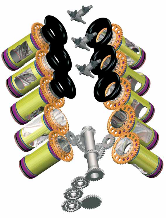
With a pair of balance webs secured on the crankshaft, the inertia force is perfectly balanced, the inertia moment is zero (all cylinder axes are coplanar), as for the inertia torque, it is almost zero (dozens of times smaller than in a Boxer with 2 or 4 cylinders).
In comparison to the best V-8 four-stroke engines, this 4-cylinder 2-stroke Cross Radial PatAT engine is better balanced from any point of view: zero free inertia force instead of a small 4th order unbalanced inertia force in the V8, half inertia torque than the V-8, equal intervals between successive combustions.
If something is unclear, please let me know to further explain.
You also write:
“I don't understand how your PatRoVa overcomes the sealing challenge that all rotary valves come up against.”
When you have to deal with tons of force pressing outwards (relative to the combustion chamber) the rotary valve and its bearings, it is impossible to maintain the required small / tiny clearance in order to achieve good sealing and small leakage.
.
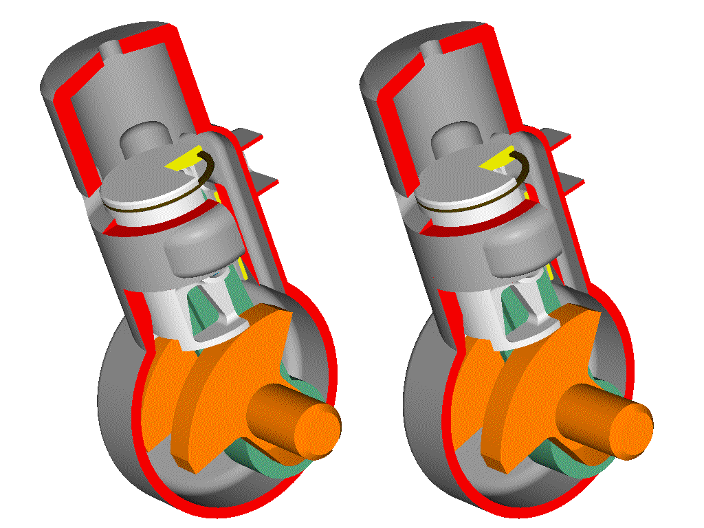
The PatRoVa rotary valve is different than all other rotary valves.
Compare it to, say, the Bishop – Cross rotary valve that came near to success in Formula1 (if the F1 rules were not changed to abandon the rotary valves, it could be the permanent winner now).
The Bishop rotary valve is a thin cylinder with an oblique separator at its middle, with the one side being red-hot and with the other side being cool. During combustion, the two bearings of the Bishop –Cross rotary valve receives a huge force (like 3 tons upwards). The two bearings are at the sides of the cylinder, i.e. at some 100+ mm from each other, with the one bearing running too hot. The valve bends due to the force load due to the high combustion pressure, and distorts due to its highly asymmetric structure and due to its highly asymmetric thermal loading.
It is impossible to keep the required tiny clearance without using sealing means. Sealing means means need for lubrication, extra friction, wear, cost etc.
Despite all these sealing problems, despite the need for cooling the exhaust side / exhaust bearing, despite the side located spark plugs (the “window” between the valve and the combustion chamber covers the central part of the bottom of the cylinder head), despite the added complexity associated with the driving of the Bishop –Cross rotary valves (count how many gearwheels and bearings and space are required):
it came near to success (some 10% more power than the best poppet valve Formula1 engines, according Mercedes and Ilmor)
To put it differently: the minimum required clearance of the big diameter bearings (big diameter because the working medium passes through them) of the Bishop – Cross rotary valve is more than the tiny clearance required for a decent sealing.
In comparison, the symmetric and extremely robust structure of the PatRoVa rotary valve, the zero total force it receives due to the high pressure in the combustion chamber, the independence of its sealing clearance from the clearance of its bearings, its independence from deformations along the two – of the three – dimensions, the from the combustion chamber, etc, etc, distinguish it from the rest rotary valves.
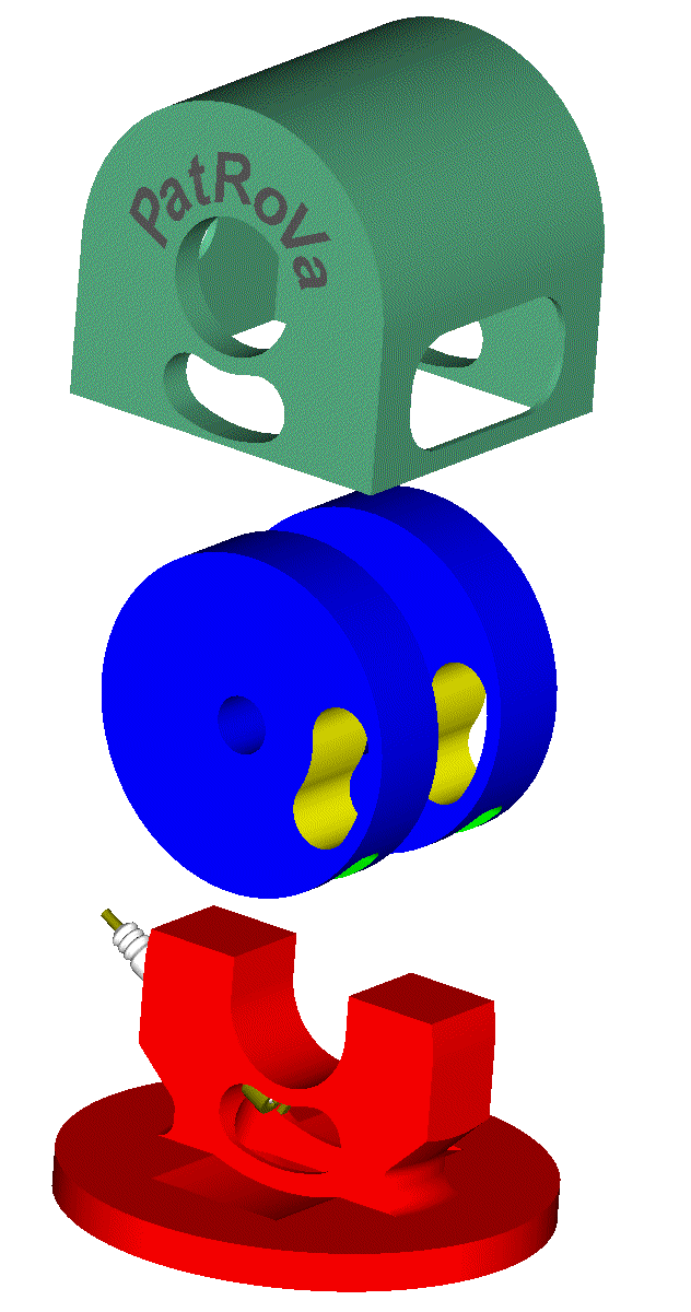
I hope it is now more clear the difference between the PatRoVa rotary valve and the rest rotary valves of the state-of-the-art.
Thanks
Manolis Pattakos