Front wing developments

Here are our CFD links and discussions about aerodynamics, suspension, driver safety and tyres. Please stick to F1 on this forum.

Am I just wasting my time?

Yes
1
10%
No
9
90%
 
Total votes: 10

User avatar
megz
1
Joined: 14 Mar 2007, 09:57
Location: New Zealand

Front wing developments

Post

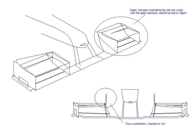
I often do little sketches of various parts of F1 cars in my spare time but I just some quick mock ups of some ideas I had in paint. Any idea if, firstly, they'd be legal, and secondly if they'd be beneficial at all.

Image

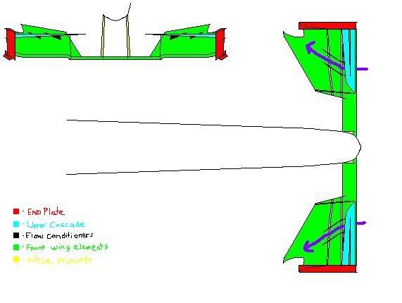
The top one shows front wing cascades akin to the old upper elemented rear wings circa 2003 and the bottom shows upright flow conditioners atop the cascades which could function like BMW's one hit wonder twin tower concept.

Image

This is a pretty coloured one. :lol: would it be possible to further direct airflow around the front wheels using especially sculpted front wing planes which actively channeled air around the front tyre as shown here? To aid to the amount of air diverted could flow conditioners be placed below the front wing cascades? I imagine this would cost downforce unless you could re harness the air downstream around the sidepod area but would a solution such as the above be beneficial in a place like Monza?

kilcoo316
kilcoo316
21
Joined: 09 Mar 2005, 16:45
Location: Kilcoo, Ireland

Re: Front wing developments

Post

1. The cascade wings - or multi-element wings - are only run when the primary element has so much curvature, there is a real risk, or there is, separation.

Having multiple elements helps to keep the flow attached for a bit longer.


2. The vertical flow conditioners... no need for them as there is no real transverse velocity field to affect.


3. Sculpted front wing - the teams are already doing this - note also the wing fences under the front wings already, and the presence of transverse "gurney flaps" at the end of them.


A) A potential area of development is inducing a downforce creating flow field around the front wing centre section...

By using splayed front wing pylons, the local airspeed above the wing can be slowed and by mounting the wing ahead of the nose cone itself (a more agressive interpretation of the toyta nose) this slower air will not create lift on nose, but only downforce from the wing.

I'm not sure how the regs in this area are fixed though.


B) Rear wheel stagnation point - given that it is a rotating wheel, interfering with the stagnation point and moving it upwards would result in a reasonable amount of downforce increase at the back (through effectively reducing the lift of the rear wheels)... better still, its unsprung downforce. This is probably what McLaren are trying to do with the floor cutting, but there are a number of different means of achieving the same thing, including a splitter mounted ahead of the wheel itself.

A future development that may occur is partial venting of the radiator exhaust in this area to manipulate the local flow. Short term, with the double diffuser ruling opening up the entire step plane to perforations for underfloor pressure manipulation, there could be numerous vents appearing at various areas of the sidepods - areas of high convex surface curvature where local flow speed should be high and thus static pressure low.

delsando
delsando
0
Joined: 03 Nov 2008, 11:18
Location: Fra

Re: Front wing developments

Post

Sorry i had to use this post for my question (couldn't be bothered to make a new post)

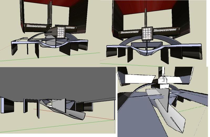
I also makes sketches during my spare time, this is one of them.

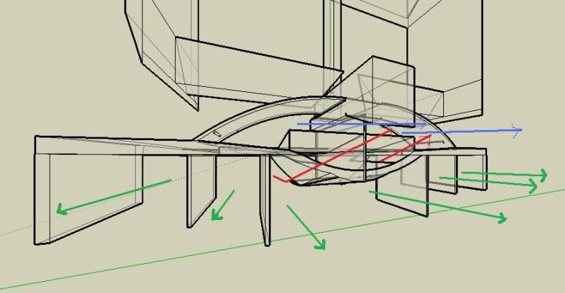
My proportions of size of the diffuser should be correct,anyways is it legal/illegal to have a "scoop" originating from the of the floor and extending above the central part of the diffuser?. Is this effective in terms of downforce and is the drag >.
Image


Image


blue= air releasing over the central part of diffuser this air might be coming from the upper floor,exhaust, over/around sides of engine cover.

red is the air originate from the "scoop"

green is the from the underfloor.

In the central part of diffuser the majority of air is from the scoop releasing on the 2ns deck above the central section, and remaining air escapes around the scoop releasing at the central part of diffuser.

I don't have engineering/aero background so don't be to harsh, i just like creating conceptual ideas. btw used goggle sketchup.
"The danger sensation is exciting, the challenge is to find new dangers." Ayrton Senna
kilcoo316
kilcoo316
21
Joined: 09 Mar 2005, 16:45
Location: Kilcoo, Ireland

Re: Front wing developments

Post

It would be illegal as the floor has to be flat ahead of the rear axle.

bar555
bar555
10
Joined: 08 Aug 2007, 18:13
Location: Greece - Athens

Re: Front wing developments

Post

Wasting your time ? OF COURSE NOT

megz , delsando
great sketches =D>

Once I tried it myself as well , but i occasionally try to design an idea of mine nowadays


Eagerly to see more of your sketches
Future is like walking into past......

Blog : http://formula1techandart.wordpress.com/
Twitter :http://twitter.com/bar555onF1

User avatar
megz
1
Joined: 14 Mar 2007, 09:57
Location: New Zealand

Re: Front wing developments

Post

Image

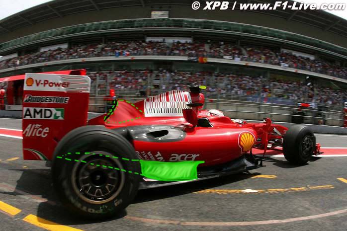
The car centreline rule which was the grey area that Williams used to place their blades in - would that cover the airheating vents i've edited onto the Ferrari where their slits were for the Spanish GP?

Also is the green duct I've edited poorly onto the bottom of the sidepod could that be used to feed the upper part of the diffuser or is the duct outside of the regulations?

kNt
kNt
0
Joined: 22 Jan 2008, 17:32

Re: Front wing developments

Post

The upper thing could be used, at least if it is continued further back.

The lower duct wouldn't bring any benefit as they can't make holes in the floor that far upfront.