My F1 car - LegendaryM

Post here information about your own engineering projects, including but not limited to building your own car or designing a virtual car through CAD.
User avatar
LegendaryM
3
Joined: 11 May 2009, 21:56

Re: My F1 car

Post

some of the things on it, like the mini diffuser in front of the wheels, i am not sure if they will work because they are just my guess at what will be effective and what will help the overall aerodynamics. At the moment im just working on new rear wing supports.
MRVC: Tolo Racing

wesley123
wesley123
204
Joined: 23 Feb 2008, 17:55

Re: My F1 car

Post

I would love to see a CFD for this.

I beleive lots of things are illegal, the horizontal fin on the ingine cover i believe is illegal, and also the double side pod fins are.

I believe you can create a more efficinet car if you allow more air around the front wheels, as now air will hit the front wheels in turning. The fins around the head support are illegal i think(same as why williams had to took them off.

I would add turning vanes under the nose and a complex splitter, also the floor section around the rear wheels need some more.
"Bite my shiny metal ass" - Bender

ESPImperium
ESPImperium
64
Joined: 06 Apr 2008, 00:08
Location: Glasgow, Scotland

Re: My F1 car

Post

Image

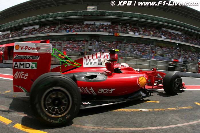
You have been thinking about something i was thinking about the other day before FP3 in Barcelona. The thing coming up to the rear wing from the engine cover. I was thinking if that was the legal width that was allowed, say the same overall width that the mid wing on the air box on the current Renault R29, that could increase airflow to the rear wing. And could especially work well with the rear wing that BMW Sauber introduced on the F1.09 at Barcelona.

And the floor holes are a much more elegant way of getting air under the floor for the diffuser to work better and more efficently than the McLaren cuts. I was thinking, is it leagal to use a Brake Duct design here, as that would put spoonfuls more air under the floor, making more downforce, and also making it work more efficently???

There is one other idea that i would like to see, and that is the front wing struts go the whole way allong the length of the nose, with shark gills on them to try and create more aero efficency here as well, maybes end it in a fing shape to try and get the air arround the sidepods as well.

Some really nice ideas there, a few are illegal, but a few others are also workable to gain a couple of extra % points of aero, whitch will be shown on a cars times on track.

User avatar
LegendaryM
3
Joined: 11 May 2009, 21:56

Re: My F1 car

Post

Image
1. The nose is wide and of about medium height, the front wing is similar to brawns, though not exactly the same and the endplates direct air outside the wheels and are similar to ferrari's pre barcelona (though I plan to update them)
2. The wing mirror is similar to brawns. I am quite certain that the sidepod fins, aswell as 3 and 5, are legal due to the loopholes in article 3.8.4;

the volume between 50mm forward of the rear wheel centre line and 300mm rearward of the rear
face of the cockpit entry template, which is more than 25mm(5 is 25mm wide) from the car centre line and more than
100mm above the reference plane ;

- the volume between 300mm rearward of the rear face of the cockpit entry template and the rear face
of the cockpit entry template, which is more than 125mm from the car centre line and more than
100mm above the reference plane ; (3 fits in here)

- the volume between the rear face of the cockpit entry template and 450mm forward (the sidepod fins are more than 450mm forward) of the rear face of
the cockpit entry template, which is more than 350mm from the car centre line and more than 100mm
above the reference plane.

The fins, especially the horizontal part, is designed to direct the air away from the rear wheels, similar to last years flip ups.
3. This fin is designed to be similar to mclarens viking horns, yet fit into the 09 regulations.
4. this is a mini diffuser which i have not tested so i dont know if it will work. it is legal because you cannot see any bodywork when viewing it from below.
5. this thin fin is designed to bring some air up from lower down so it can interact with the rear wing
6. New rear wing supports which i designed today, aswell as BMW-style upper elements.
I have tried to make sure everything on it is legal (when im designing it i always have the regulations open)

EDIT: If anyone wants it, I have uploaded the 3d model in solid edge viewer, which can be viewed in a browser:
http://www.filefactory.com/file/aghfbc3/n/DR09B_exe
MRVC: Tolo Racing

tommylommykins
tommylommykins
-1
Joined: 12 May 2009, 22:14

Re: My F1 car

Post

Hiya

I think you might have left out a very important part of the front mechanical setup..

Steering arms?

User avatar
LegendaryM
3
Joined: 11 May 2009, 21:56

Re: My F1 car

Post

tommylommykins wrote:Hiya

I think you might have left out a very important part of the front mechanical setup..

Steering arms?
yeah I think you're right. Ill add them to my to do list, research steering arms and try and get them done tomorrow.
MRVC: Tolo Racing

The Thorn
The Thorn
0
Joined: 13 Apr 2009, 22:01

Re: My F1 car

Post

I might be wrong, but I think the flip-up on the engine cover to the rear wing will cause a lot of spoiled air, making the rear wing less efficient.
Also, part numer 3 in your last picture seems to be a air laminator in a area where there is not mucht to laminate. You might be better off by getting them off, because all parts create drag. It might be something to consider, when you have the abillity to test this in CFD.

But I am very impressed by your design. A tripple deck diffusor might be something, and I'm very eager to know how it works.

User avatar
machin
162
Joined: 25 Nov 2008, 14:45

Re: My F1 car

Post

At the beginning of the season I did something similar... I've since amended it to include a double deck diffuser...

The way I did it was to create a block for the car body that meets all the body dimension rules (mainly using extrusions) and then cut the car shape out of that block... (imagine a block of clay and then filing that down)...

Its not as detailed as Legendary M's, although from the rear view you can see I have a gearbox model (and a an engine but you can't see that) and of course a man of my dimensions to fit into it!

Image
COMPETITION CAR ENGINEERING -Home of VIRTUAL STOPWATCH

User avatar
machin
162
Joined: 25 Nov 2008, 14:45

Re: My F1 car

Post

You can also see from the rear view of mine that I have the same problem as Ferrari; the upper deck of my double deck diffuser is blocked by the gearbox/rear impact structure! Will fix that if I get time!
COMPETITION CAR ENGINEERING -Home of VIRTUAL STOPWATCH

User avatar
megz
1
Joined: 14 Mar 2007, 09:57
Location: New Zealand

Re: My F1 car

Post

Another very quickly and poorly edited picture, but if these fins were legal wouldn't the additional airflow - which would be consistant and of higher temperature - improve the effeciency of the rear wing by energising the airflow?

Could they be be joined by small wing to a sharkfin to further increase downforce?

Image

User avatar
slimjim8201
12
Joined: 30 Jul 2006, 06:02

Re: My F1 car

Post

Obviously, I would love to grab the full MCAD models from either of you guys...

User avatar
LegendaryM
3
Joined: 11 May 2009, 21:56

Re: My F1 car

Post

slimjim8201 wrote:Obviously, I would love to grab the full MCAD models from either of you guys...
What format would you like me to send it in. I'm just making some changes now to the diffuser but I could send it when I have finished doing that
MRVC: Tolo Racing

User avatar
machin
162
Joined: 25 Nov 2008, 14:45

Re: My F1 car

Post

slimjim8201 wrote:Obviously, I would love to grab the full MCAD models from either of you guys...
Mine's made on Solidworks... Its on my other computer, but I think the files could be quite big.... If you let me know a format I could see about converting it...

...Having said that I'm not sure what you'll gain from either model; Not sure about Legendary M's but mine has solid radiators... so the pressure build-up in front of them will be much higher than they would be, and also there'll be no flow out the exits. The side-pod radiator opening and engine intake opening areas are obviously guesses too, so direct comparison is pointless..... the result is that flow over and through my model wouldn't be very indicative of the flow around an actual car built to the same dimensions......
COMPETITION CAR ENGINEERING -Home of VIRTUAL STOPWATCH

fabio999
fabio999
0
Joined: 14 May 2009, 00:02

Re: My F1 car

Post

Hi, i have to say that is a very nice design...and i can imagine how much effort it required to you!!

Are you, by chance, interested in someone that can run some cfd calculations on your model?!? :) ...someone like me for example (i'm an aerodynamics engineer)?!? :)

Let me know if your interested!!

Bye bye,
Fabio

User avatar
LegendaryM
3
Joined: 11 May 2009, 21:56

Re: My F1 car

Post

I have managed to make some changes to the vertical opening on the diffuser, which feeds the upper central deck. These changes consisted of an entirely new rear crash structure
Image

@fabio999 or slimjim8201 - what format would you like me to send the model in
MRVC: Tolo Racing