Hi guys,
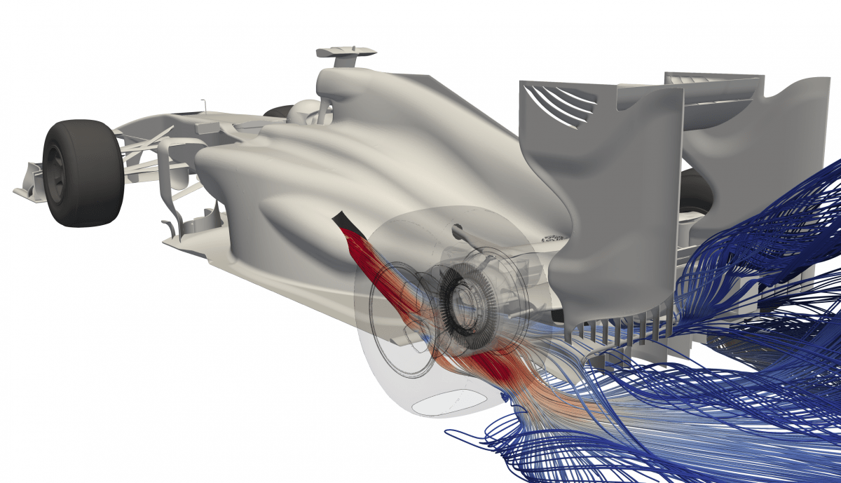
it is time for me to also get involved in these discussions. regarding the tire wake. There was also a comment in the other thread about this. There are many factors that play a role. I think the comment was not totally right as the person did not seem to notice that the slice shown was very close to the floor and not in the middle of the wheels where the wake would have appeared much more pronounced. Now, is our wake super realistic? Who knows, but the thing is it will never really be. Be run rather coarse steady state simulations. The wake will only look more realistic when using averaged transient simulations. This however will blow up computing times and there I think we currently have a nice tradeoff.
I am happy to work on the tire CAD though and have a more realistic tire patch f that is so important for you guys. Here are images that I think help more that what was shown here so far:
https://www.racetechmag.com/2019/03/wil ... s-dilemma/

I have a feeling, I mostly have to change the camber of the front wheels.
Now about cooling: I am open to discuss that with you guys as well. Now why do we run the cooling part the way we do?
First of all it is important to look at how a real F1 works in regards to thermal management. The cars have turbo charged ICEs. These ICEs and additional components demand a number of cooling flows, I will list a few:
- Heat exchanger(s oil/water) for the engine block
You can find more here:
https://motorsport.tech/formula-1/car-c ... -explained
Now how can we model all this in CFD? For one, we can simply create a porous medium for every heat exchanger in question and model it that way. This would work but please keep in mind that we have to keep things simple to a certain extent. Many F1 cars will not be symmetric and some teams might choose to put some of the HXs into the center of the car fed by to top inlet. Allowing you guys to go for configurations like this will make thing far to complicated and turn the challenge more into a thermal management challenge rather than an external aerodynamics challenge. So what we do is simply have on heat exchanger at one side of the car, as we are utilizing symmetry, to keep the run time low, that represents all cooling needed for the entire car. This is a better simplification that you might think at first. But a team running a water and an oil cooler behind each other (that is how it would be done in F1) would have two porous media right behind each other, this is pretty much just like running one thicker one, in the simulation it makes no real difference. The only thing you are missing out on is the possibility to have HXs in the center of the car. But this is simply out of scope. To allow it, we would first of all have to run a porous medium for every HX and then actually account for the shift in CoG and then also deal with the actual air intake. So I hope it is clear that we will keep the current layout of the cooling simulation as it is.
Now, what we can discuss is the demand of cooling flow and the porous media resistance. I have gone through the numbers more than once and even consulted with a previous F1 engineer and I am happy with what we have. So if anyone thinks something here is unrealistic, please present cold hard numbers to support what you are saying. Estimate the complete cooling demand, how much air would be needed or show me some pressure drop data from real F1 HX cores.

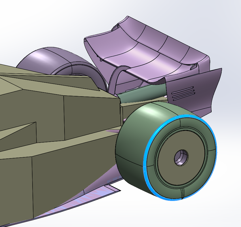
), the geometry 2023 will inlcude small updates, in order to match the real tyres shape. More specifically, the edge of the rubber will be more rounded for both rear and front wheels, this will have a significant impact on wake.


