Ferrari Power Unit Hardware & Software

All that has to do with the power train, gearbox, clutch, fuels and lubricants, etc. Generally the mechanical side of Formula One.
AR3-GP
AR3-GP
365
Joined: 06 Jul 2021, 01:22

Re: Ferrari Power Unit Hardware & Software

Post

This is another chrono GP fantasy

The cylindrical box that they claim is the compressor, is the reaction engine intercooler.
A lion must kill its prey.

User avatar
aleks_ader
90
Joined: 28 Jul 2011, 08:40

Re: Ferrari Power Unit Hardware & Software

Post

If was on me Chromo GP should be banned.. :D At least not in this thread.
"And if you no longer go for a gap that exists, you're no longer a racing driver..." Ayrton Senna

johnny comelately
johnny comelately
110
Joined: 10 Apr 2015, 00:55
Location: Australia

Re: Ferrari Power Unit Hardware & Software

Post

aleks_ader wrote:
02 Feb 2023, 02:29
If was on me Chromo GP should be banned.. :D At least not in this thread.
And then what would you chaps have to whinge about :wink:

johnny comelately
johnny comelately
110
Joined: 10 Apr 2015, 00:55
Location: Australia

Re: Ferrari Power Unit Hardware & Software

Post

AR3-GP wrote:
02 Feb 2023, 00:08
This is another chrono GP fantasy

The cylindrical box that they claim is the compressor, is the reaction engine intercooler.
Some say that the visible circular plate axially congruent with the compressor centreline is a reaction engine intercooler.
If so, that plate has no coolant feed that end, so it must be at the other?
OK, as the compressor discharge is necessarily radial how does it end up entering the intercooler axially?
Possible but with coolant pipes at that end as well it would make it very difficult packaging wise.
Or have they reverse fed the intercooler? Assuming the standard one is centre fed.
(See my recent post in "Interesting Stuff" topic)
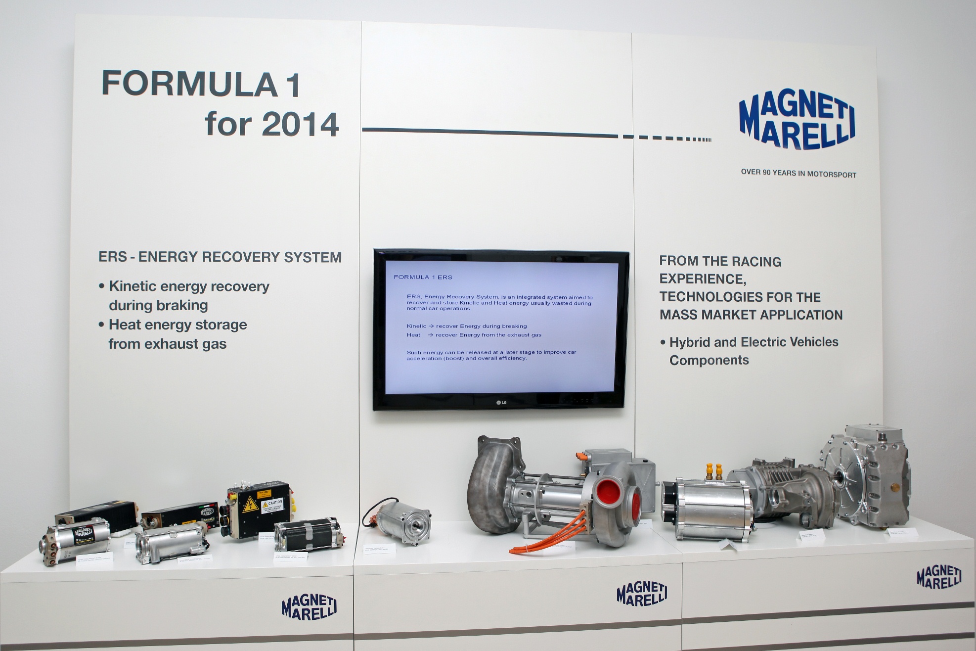
Image
And to muddy the waters a bit more
Image
https://www.magnetimarelli.com/press_ro ... hnological

saviour stivala
saviour stivala
51
Joined: 25 Apr 2018, 12:54

Re: Ferrari Power Unit Hardware & Software

Post

The chrono GP fantasy rendering conveniently places turbocharger components on the power unit where it suites their fantasy narrative. While actual photos shows their actual position, The Nicolas Carpentier front of engine photo shows the carbon fiber housing of the reaction engines type of intercooler mounted much lower than the possible lowest centerline mounting of the compressor/MGU-H/turbine setup.

User avatar
Blackout
1566
Joined: 09 Feb 2010, 04:12

Re: Ferrari Power Unit Hardware & Software

Post

Those chrono GP 3d renders are annoying indeed. They look nice and the guy who makes them is talented at making 3d renders, but he has absolutely no clue how an F1 engine works and doenst fully understand what he's modeling. It obvious in the way he connects some engine components together... sometimes he does absurd things with the non visible parts...

AR3-GP
AR3-GP
365
Joined: 06 Jul 2021, 01:22

Re: Ferrari Power Unit Hardware & Software

Post

Blackout wrote:
06 Feb 2023, 15:37
Those chrono GP 3d renders are annoying indeed. They look nice and the guy who makes them is talented at making 3d renders, but he has absolutely no clue how an F1 engine works and doenst fully understand what he's modeling. It obvious in the way he connects some engine components together... sometimes he does absurd things with the non visible parts...
The amusing thing is as you say, the guy is brilliant with the rendering skills, but lacks the technical insight to perform a sanity check on the visualization.

If this guy knew his technical stuff, Ferrari would have hired him just to stop him posting their designs in 4K glory all over the internet :lol:
A lion must kill its prey.

saviour stivala
saviour stivala
51
Joined: 25 Apr 2018, 12:54

Re: Ferrari Power Unit Hardware & Software

Post

It is not enough for the guy to know the technical side, what he needs is know the FERRARI actual layout. All he have been doing is pure imagination and speculate accordingly. Nevertheless, his imagination and speculating method seem to work for him with people at a certain technical level, If it didn't work for him he would not be repeating his imaginative speculations. This is a pure classic of that saying that no part of the cow goes to waste.

User avatar
Stu
Moderator
Joined: 02 Nov 2019, 10:05
Location: Norfolk, UK

Re: Ferrari Power Unit Hardware & Software

Post

The saddest thing of all is that people that do not know/understand how these work will take it as fact and insider knowledge. I’m fairly certain that the renders show the airflow totally incorrectly anyway, regardless of the assumed construction.
Photos of the ICE clearly show pipework running forwards through the V to the cylindrical cooler (mounted at the front). This was change from previous versions which seems to allow for improved flow after the charge-cooler.
Even with 4.5bar of boost, improvements in flow generate increased efficiency.
Perspective - Understanding that sometimes the truths we cling to depend greatly on our own point of view.

johnny comelately
johnny comelately
110
Joined: 10 Apr 2015, 00:55
Location: Australia

Re: Ferrari Power Unit Hardware & Software

Post

Hopefully the digression of the little echo chamber about the Chrono renders is over and we can get back to working out the turbo conundrum.
If what SS postulated is correct that the Reaction Engine intercooler is lower that the centreline of the turbo itself, my imagining of its length would be 200mm + how would that fit in front of the block?

johnny comelately
johnny comelately
110
Joined: 10 Apr 2015, 00:55
Location: Australia

Re: Ferrari Power Unit Hardware & Software

Post

In relation to intercoolers this video is showing some advances in heat exchangers using generative design from thermodynamic inputs and being made possible by additive manufacturing, all in the same envelope. Wondering if the simulations can pick up bubble forming in the new designs one of which is sinusoidal surfaces.
Depending on the fluid velocity and angle wouldnt a sinusoidal curve (of necessarily smallish curvature/radius) produce turbulent flow with separation, leading to bubbles?

Hoffman900
Hoffman900
211
Joined: 13 Oct 2019, 03:02

Re: Ferrari Power Unit Hardware & Software

Post

These are several papers that were co-authored by Ferrari, and use measured data to validate their models, and present a few different strategies involving the Formula 1 PU circa 2017:

Time-Optimal Low-Level Control and Gearshift Strategies for the Formula 1 Hybrid Electric Powertrain
https://www.mdpi.com/1996-1073/14/1/171
Today, Formula 1 race cars are equipped with complex hybrid electric powertrains that display significant cross-couplings between the internal combustion engine and the electrical energy recovery system. Given that a large number of these phenomena are strongly engine-speed dependent, not only the energy management but also the gearshift strategy significantly influence the achievable lap time for a given fuel and battery budget. Therefore, in this paper we propose a detailed low-level mathematical model of the Formula 1 powertrain suited for numerical optimization, and solve the time-optimal control problem in a computationally efficient way. First, we describe the powertrain dynamics by means of first principle modeling approaches and neural network techniques, with a strong focus on the low-level actuation of the internal combustion engine and its coupling with the energy recovery system. Next, we relax the integer decision variable related to the gearbox by applying outer convexification and solve the resulting optimization problem. Our results show that the energy consumption budgets not only influence the fuel mass flow and electric boosting operation, but also the gearshift strategy and the low-level engine operation, e.g., the intake manifold pressure evolution, the air-to-fuel ratio or the turbine waste-gate position.
Low-level Online Control of the Formula 1 Power Unit with Feedforward Cylinder Deactivation
https://arxiv.org/abs/2303.00372
Since 2014, the Fédération Internationale de l'Automobile has prescribed a parallel hybrid powertrain for the Formula 1 race cars. The complex low-level interactions between the thermal and the electrical part represent a non-trivial and challenging system to be controlled online. We present a novel controller architecture composed of a supervisory controller for the energy management, a feedforward cylinder deactivation controller, and a track region-dependent low-level nonlinear model predictive controller to optimize the engine actuators. Except for the nonlinear model predictive controller, the proposed controller subsystems are computationally inexpensive and are real time capable. The framework is tested and validated in a simulation environment for several realistic scenarios disturbed by driver actions or grip conditions on the track. In particular, we analyze how the control architecture deals with an unexpected gearshift trajectory during an acceleration phase. Further, we demonstrate how an increased maximum velocity trajectory impacts the online low-level controller. Our results show a suboptimality over an entire lap with respect to the benchmark solution of 49 ms and 64 ms, respectively, which we deem acceptable. Compared to the same control architecture with full knowledge of the disturbances, the suboptimality amounted to only 2 ms and 17 ms. For all case studies we show that the cylinder deactivation capability decreases the suboptimality by 7 to 8 ms.
Model-Based Pre-Ignition Diagnostics in a Race Car Application
https://www.mdpi.com/1996-1073/12/12/2277
“Since 2014, Formula 1 engines have been turbocharged spark-ignited engines. In this scenario, the maximum engine power available in full-load conditions can be achieved only by optimizing combustion phasing within the cycle, i.e., by advancing the center of combustion until the limit established by the occurrence of abnormal combustion. High in-cylinder pressure peaks and the possible occurrence of knocking combustion significantly increase the heat transfer to the walls and might generate hot spots inside the combustion chamber. This work presents a methodology suitable to properly diagnose and control the occurrence of pre-ignition events that emanate from hot spots. The methodology is based on a control-oriented model of the ignition delay, which is compared to the actual ignition delay calculated from the real-time processing of the in-cylinder pressure trace. When the measured ignition delay becomes significantly smaller than that modeled, it means that ignition has been activated by a hot spot instead of the spark plug. In this case, the presented approach, implemented in the electronic control unit (ECU) that manages the whole hybrid power unit, detects a pre-ignition event and corrects the injection pattern to avoid the occurrence of further abnormal combustion”
All our interesting, but the first paper is probably the best of these and goes over strategies on how the PU's are deployed and manage the hybrid elements with the IC, to produce the best lap time. This information obviously wouldn't be current, especially in light of Ferrari moving to a "super fast combustion concept (TJI / compression ignition hybrid), but provides the best insight of PU's in this rule set that's been published to date.

saviour stivala
saviour stivala
51
Joined: 25 Apr 2018, 12:54

Re: Ferrari Power Unit Hardware & Software

Post

FERRARI's named 'superfast combustion' concept does not necessary mean (TJI/COMPRESSION IGNITION HYBRID). Implying that FERRARI's superfast combustion concept uses two types of combustion process at the same time is only your perceived imagination, unless you can produce prof of what FERRARI is actually using.

User avatar
KAIZEN
80
Joined: 14 Aug 2018, 01:56
Location: Japan

Re: Ferrari Power Unit Hardware & Software

Post

KAIZEN wrote:
13 Nov 2022, 08:29
johnny comelately wrote:
12 Nov 2022, 12:11
Anyone care to explain how this compressor works.
And if you jump in and say the ChronoTV stuff is nonsense that is ok, just sketch or explain how the real thing works because in the associated photos that end plate does exist
https://www.youtube.com/watch?v=XUXiiB7LgHE
https://images-wixmp-ed30a86b8c4ca88777 ... vVHsiwMVlc
1.Never believe the technical analysis of Chrono GP
2.The turbine position is predictable in the exhaust, but its position is very high and does not coincide with the circular object ahead.
3.Ferrari has said it has not changed its turbine layout.
4.Since there is a turbine, compressor, and MGU-H in the rear, the duct from the plenum chamber protrudes to the side.
5.The split type Honda has a rear space in the V bank, so the duct fits in without sticking out sideways.

https://i.imgur.com/iptHHJo.jpeg

https://i.imgur.com/apQwqGO.jpeg
I'm guessing the connection from the compressor to the intercooler goes through the bottom of the V bank.

User avatar
vorticism
323
Joined: 01 Mar 2022, 20:20

Re: Ferrari Power Unit Hardware & Software

Post

johnny comelately wrote:
03 Feb 2023, 23:34
Image
Pretty sure this is exactly what Ferrari are using. Water lines in and out on one face. Airflow as shown here.
𓄀