Mmgnt wrote: ↑19 Feb 2024, 04:14
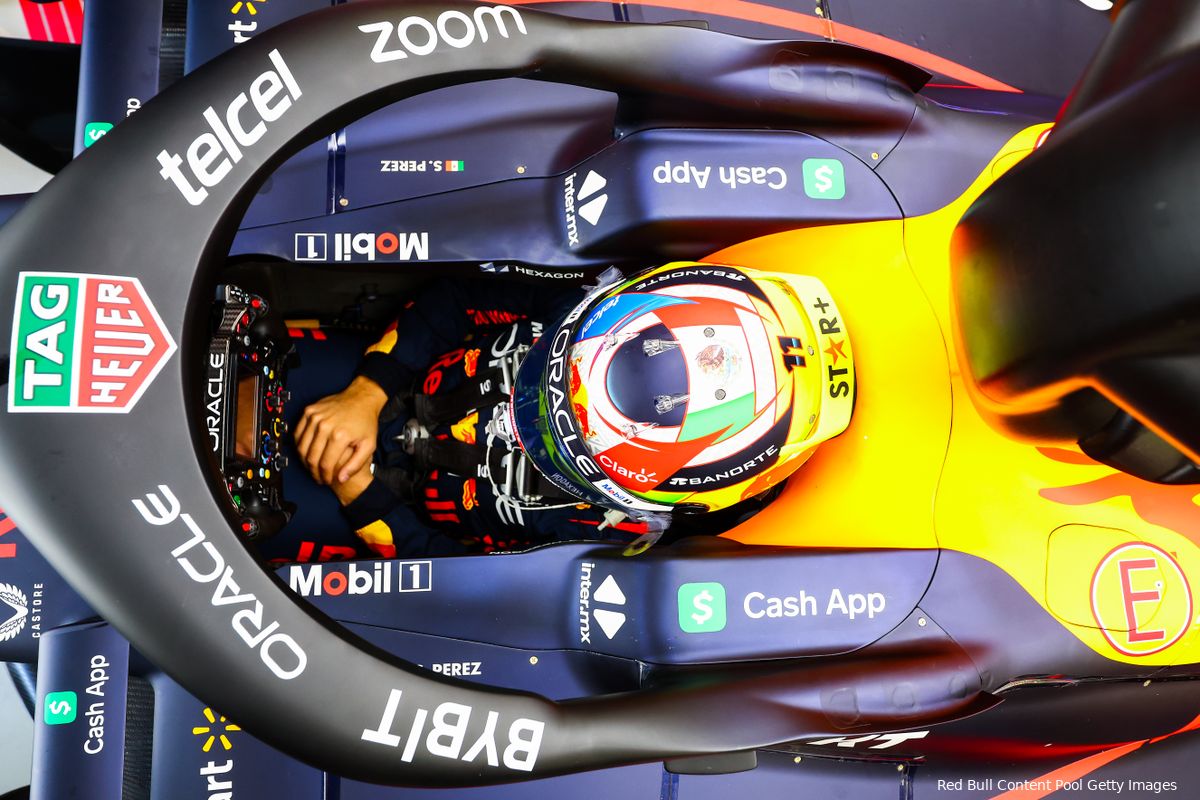
Here's my guess: there are small rads in the sidepods, as well as somewhere in the cannon area. The S-ducts flow into the cannons, coming up at the bulge.
The seating location appears to permit it as it'd be behind the driver seat/shoulders
Looking at the comparison pic again, those cannons are just
way too huge to not have something significant underneath IMO. They even bulge out immediately after the halo mount, as soon as possible (I assume, given Halo mounting restrictions). From an aero perspective I assume this would introduce unnecessary drag, meaning they must have a reason?
It also looks like it might fit between seat & fuel cell? Not sure what's there (carbon area in front of the light brown cell)
https://i.imgur.com/4QspHSd.png
https://i.imgur.com/Etldp2U.png
https://r.testifier.nl/Acbs8526SDKI/res ... 4e43ed.jpg
https://i.imgur.com/oz7PYOO.png
Let's say the engine is fed air from the vertical intakes and pretend the other sidepod intake is a dummy meant to throw teams off the scent.
To match other cars redbull would need a really efficient air to air intercooler on top of the engine.
For the engine intakes refer to @vorticism's post and diagram.
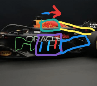
Now excuse my poorly annotated drawing, the purple rectangle is the engine block, the small green lines represent the engine intake and the turbo compressor, the thick green line represents the air to air intercooler, the blue rectangle represents the transmission and the yellow represents the path the air would take after cooling the compressed air.
This can work but my question is with a limited budget why would they pursue this? The tradeoffs if not done properly are poor reliability, a high center of gravity, increased drag and more weight.
The weight and center of gravity are self explanatory. For the reliability part, refer to the arrow at the top and the three lines in the engine. That represents the fact the two cylinders at the front would always run the coolest while the rear two will run hotter because they are ingesting hotter air. This means that two of the six cylinders would be tuned to make less power because hotter air temperatures increase the risk of engine knocking. This also may make the engine suffer from more vibrations. We also should note that I didn't put in any oil coolers, engine coolers heck even the transmission cooler was omitted. All of this heat needs to be managed and yet they also need to prioritize cooling the intake air to make the most engine power. With this layout the rest of the coolers will come after the charge cooler which again won't do good for their temperatures. Good luck idling the car without overheating.
The next part is drag. Since drag is a function of speed, designers often increase the volume right after the intake to lower the air speed which would cut the drag. With this layout I am not sure if they have enough volume to play with in that area to pull off this trick. Again, think of how much they have to cool.
Lastly if it was feasible Mercedes would've gone with it to reduce the size of the sidepods at least for the w14 where they doubled down.
TLDR, it is possible, it can work but it isn't feasible.