n smikle's LMP car

Post here information about your own engineering projects, including but not limited to building your own car or designing a virtual car through CAD.
User avatar
PlatinumZealot
559
Joined: 12 Jun 2008, 03:45

n smikle's LMP car

Post

Can somebody confirm the advantages/disadvantages of longer control arms for me.
And if there are significant advantages what should determine a limit to the length of a set of control arms?

thanks


Image
πŸ–οΈβœŒοΈβ˜οΈπŸ‘€πŸ‘ŒβœοΈπŸŽπŸ†πŸ™

Racing Green in 2028

Mystery Steve
Mystery Steve
3
Joined: 25 Sep 2009, 07:04
Location: Cincinnati, OH, USA

Re: Long Control arms

Post

The length of the control arm affects camber change in roll and ride. The relative length of the control arms also have a major effect on the camber change. There isn't necessarily an advantage/disadvantage to either. The designer picks the lengths depending on what they the want the kinematics to do.

However, the width of the tub is generally constant considering the width of the drivers feet, so making the control arms longer in that case increases the track width. Playing with the track width changes your weight transfer, which is also not necessarily a minimum or maximum thing, it's what the designer wants.

User avatar
mep
29
Joined: 11 Oct 2003, 15:48
Location: Germany

Re: Long Control arms

Post

The length of the control arms affect your camber change rate and how much your instant centre moves during wheel vertical travel.
Advantage: A longer control arm reduces your camber change and your instant centre movement.

Disadvantage: Hm, longer struts are easier to buckle, this can be an issue.


BTW: This would have fit also into this threat:
viewtopic.php?f=6&t=7474

User avatar
PlatinumZealot
559
Joined: 12 Jun 2008, 03:45

Re: Long Control arms

Post

Thanks for the replies.

What really is happening is that I am doing a race car design (just for fun) and I have come to a dilemma where I can either go with really long control arms with shocks and springs mounted vertically near the chassis centre line or go with shorter controls arms with the shocks and springs mounted transversely at the front of the chassis. The First options gives a narrower chassis and better camber motion as you say, but I find that the transverse mounting is much easier to calculate and I can use a simple sway bar connected to the bellcranks(longitudinally aligned axis).

So for the long control arms skinnier chassis:

1. narrow central chassis (more aerodynamic?)
2. good camber movement
3. arms/pushrod more prone to buckling
4. heavier arms
5. shocks and springs near the centre line (less Polar MOI)
6. Complicated swaybar mounting

Short arms:
1. Wider front chassis (more drag, but a nice place to mount a large radiator)
2. shocks and swaybar are easy to mount
3. less material so lighter control arms and pushrod
4. not as good camber movement.
5.

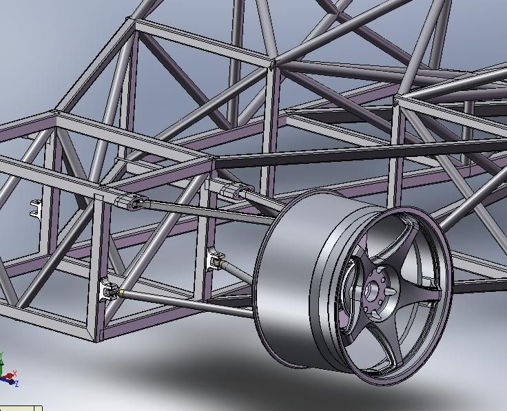
This is a picture of the car... It's supposed to a like a LMP1 except it has much longer wheel travel to handle the bumpiness of a road track.

Here is the front with the long control arms. The shocks that are to be used are 300mm to 400mm. I think the central box shown is about 500mm wide and each lower arm is about 490mm long IIRC.

looks Okay?

Image
πŸ–οΈβœŒοΈβ˜οΈπŸ‘€πŸ‘ŒβœοΈπŸŽπŸ†πŸ™

Racing Green in 2028

marcush.
marcush.
159
Joined: 09 Mar 2004, 16:55

Re: Long Control arms

Post

offtopic:sideline on the chassis:
stay away from paralellogramms in the routing of your chassis tubes ,you might be able to save a lot of those diagonal tubes that only serve to correct the mistake of doing parallel tubes....also building of the chassi wil be a lot easier as the bits ,correctly laid out and cut will all help to get the whole thing straight in the end.

also mating of some of the steel tubes will lead to severe warpage in the frame ,you need to take this into consideration when designing as i do not think its a good idea to have all these tubes preformed to get those tubes actually conform to your drawings when the chassis is finished.
so IΒ΄d say take a few hours with an experienced welder -craftsman and he will easily sort out the junk wich will not be nice to fabricate .Money in the bank even for a one off.

User avatar
mep
29
Joined: 11 Oct 2003, 15:48
Location: Germany

Re: Long Control arms

Post

Ok, that is a different story now.
In your case I would definitely go for option 2 (short control arms).
The chamber change rate by long or short a-arms should not be top priority for you.
There are many other things you can care about first.
For you first of all it is important to get a stiff and not to heavy car.
A wider front chassis will make it easier for you to get it stiff and to place components in between.
I don’t know how much time you spend with your kinematics but even there are more important things to consider than the pure a-arm length. You would probably not even notice an advantage by the reduced chamber change rate.

Two other things I noticed:
1) The lower attachment of your a-arms will put your chassis tube under bending loads.
2) The top attachment points doesn't look very solid too.
Especially the more rearward placed one. The welding seam of this outstanding tube is a likely place for a failure. Try to get rid of it or at least make some kind of triangularisation.

Image

Jersey Tom
Jersey Tom
166
Joined: 29 May 2006, 20:49
Location: Huntersville, NC

Re: Long Control arms

Post

Absolute control arm length actually does not do much for your camber curves. You can have 0 deg / inch bump camber with 4" long control arms. Camber curves are all about relative length and non-parallelism.

Control arm length does however really help scrub. Lateral motion of the tire through bump travel will give rise to changes in slip angle.. the significance of which you'll have to determine.
Grip is a four letter word. All opinions are my own and not those of current or previous employers.

marcush.
marcush.
159
Joined: 09 Mar 2004, 16:55

Re: Long Control arms

Post

Jersey Tom wrote:Absolute control arm length actually does not do much for your camber curves. You can have 0 deg / inch bump camber with 4" long control arms. Camber curves are all about relative length and non-parallelism.

Control arm length does however really help scrub. Lateral motion of the tire through bump travel will give rise to changes in slip angle.. the significance of which you'll have to determine.
exactly


as for the mounting points:

If anything, --- happens in racing.So in my view it is of importance to design all suspension pickups stiff but in a way so that in extreme cases the pickup points will brake off instead off rendering the complete frame a writeoff when pickuppoints stay attached and thr forces bend or kink the frame .But thats of course my personal view.

User avatar
PlatinumZealot
559
Joined: 12 Jun 2008, 03:45

Re: Long Control arms

Post

Ok :mrgreen: I will soon get back to the frame, I know you guys have a lot of things to say on it! Overall, the strength and shape of frame can be adjusted pretty easily so I am just trying to fully understand the workings of the suspension and the aerodynamics then the frame will be adjusted.
πŸ–οΈβœŒοΈβ˜οΈπŸ‘€πŸ‘ŒβœοΈπŸŽπŸ†πŸ™

Racing Green in 2028

User avatar
flynfrog
Moderator
Joined: 23 Mar 2006, 22:31

Re: Long Control arms

Post

you really dont want your suspension attachment in the middle of a tube like that

User avatar
PlatinumZealot
559
Joined: 12 Jun 2008, 03:45

Re: Long Control arms

Post

I know 8)
The frame seems to have everybody's attention.
She isn't going anywhere, she will be right here. lol
πŸ–οΈβœŒοΈβ˜οΈπŸ‘€πŸ‘ŒβœοΈπŸŽπŸ†πŸ™

Racing Green in 2028

User avatar
PlatinumZealot
559
Joined: 12 Jun 2008, 03:45

Re: Long Control arms

Post

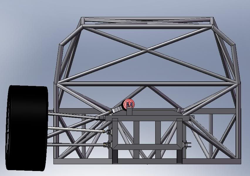
I shortened the Control arms slightly by increasing the width of the front and back ends of the frame they are still pretty long though. The major reason why I kept them so long is because of the 2m width of the car and the placement of the front and rear diffusers. After watching F1 this year I just had to have huge diffusers =P~ .

The overall width of the arms as viewed from the back. Final Ride height wont be that low for the eagle eyed amongst us. 8) still have to put a floor on.

Image

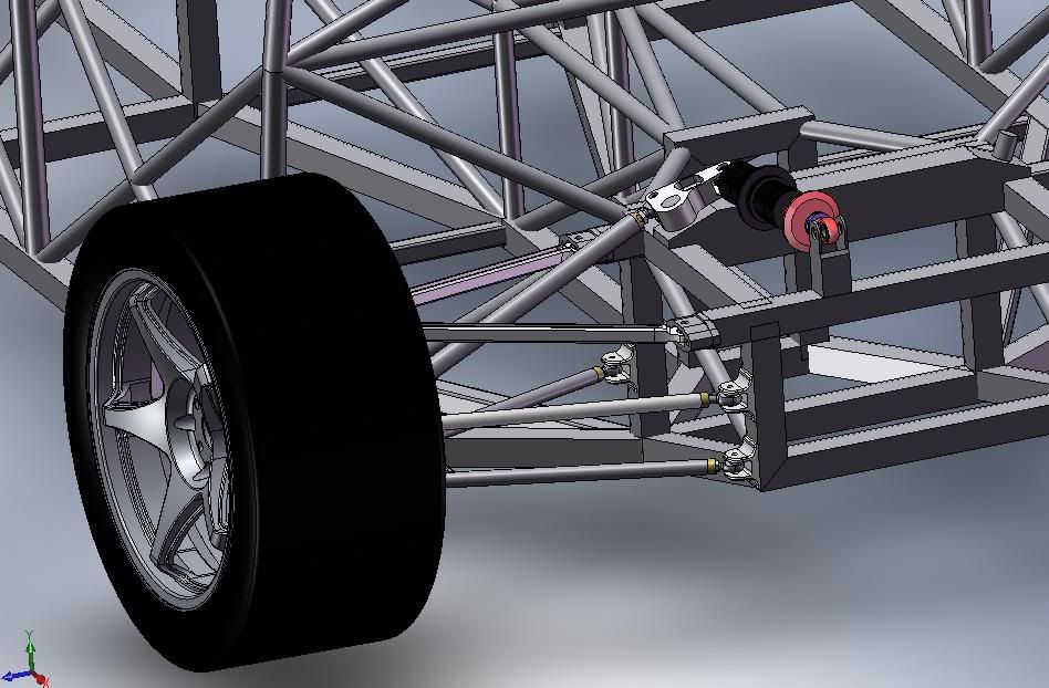
Yes the suspension mount will put a torque on the beam. It had to be mounted there because I wanted the bellcrank to rotate around a certain axis. Don't worry 8) it can be adjusted.

Image


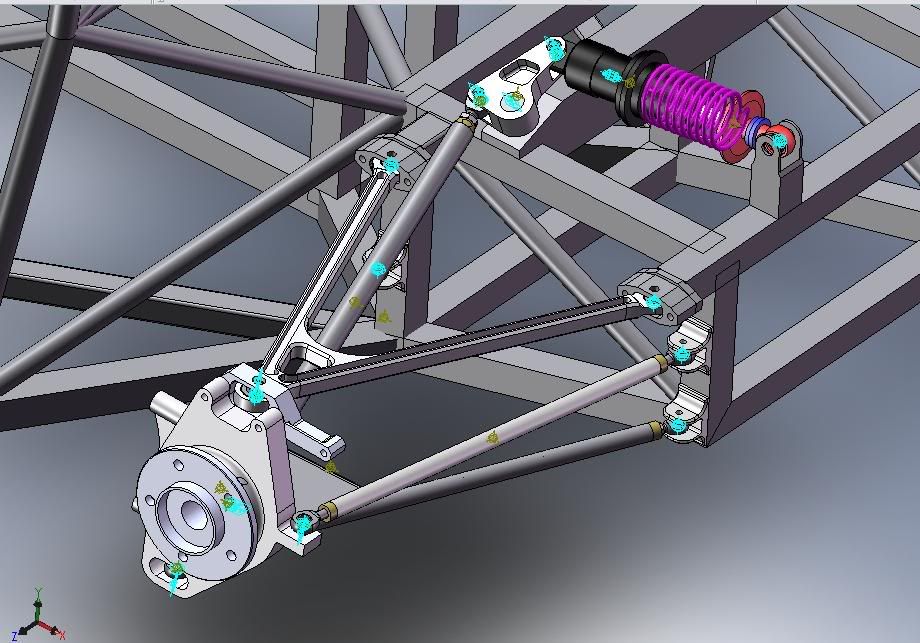
Trying to set up the motion model:

Image


The bending loads are inevitable in almost any design like this as the members are welded together(fixed-fixed beams, this is not a truss design) I know the suggestions are to minimise bending loads. But due to the aerodynamic and suspension requirements that I have, the mounting points have to place in their present locations hence the frame just has to be designed for the resulting bending loads.

Do you guys think I can locate the bell-crank outwards some more so I can get the suspension mount on top of that beam to the left of it? That bridge looking thing the bell-crank is on is a 3" x 2" box section cut up.
πŸ–οΈβœŒοΈβ˜οΈπŸ‘€πŸ‘ŒβœοΈπŸŽπŸ†πŸ™

Racing Green in 2028

Jersey Tom
Jersey Tom
166
Joined: 29 May 2006, 20:49
Location: Huntersville, NC

Re: Long Control arms

Post

That damper mount will probably either twist the tube or shear right off.

Why the weird billet a-arms?

Or the chassis tubes / roll hoops with sharp angles instead of nice bent radii?
Grip is a four letter word. All opinions are my own and not those of current or previous employers.

marcush.
marcush.
159
Joined: 09 Mar 2004, 16:55

Re: Long Control arms

Post

reference bellcrank orientation:
why do you put them this way ? your bellcrank bearings fill face a lot of thrust load in extreme bump-droop positions and of course you will not direct all forces into the damper spring this way ..i think you donΒ΄t operate at F1 style wheel movements do you? so placing the rockers with the turning axis in x direction would help to get rid of a lot of problems ,as you could feed the forces into the lower longitudinal rails directly ,lowering cg + getting rid of those two outriggers catching JTs attention...and mine as well...

I do not see a direct link between diffusser and underbody design and control arm length ,can you please enlighten us about this?

If you really try to maximise downforce I have the feeling you need to take the Audi R15 idea to the extremes in the front area ,creating a realy big slot into the chassis and make room for a huge front end diffusser- wing arrangement.your current design really does not create a favourable area for creating front end downforce ,as theres no where the air can exit aft the front wheels ...you will need a diverging passage attracting air to go if I am not totally wrong..

User avatar
PlatinumZealot
559
Joined: 12 Jun 2008, 03:45

Re: Long Control arms

Post

That damper mount will probably either twist the tube or shear right off.
I had an option to integrate a plate structure behind it to hold the wing and rear bumper that will double as a reinforcement. But after looking at it I will move it to the left onto the top long. beam.
Why the weird billet a-arms?
The top aluminum A arms, were mostly done for the hell of it. But I have seen them used on some Race cars before. It's about 2/3 lighter even with the bearings. If it were to be actually built though i would use the steel though.
Or the chassis tubes / roll hoops with sharp angles instead of nice bent radii?
This is just for the simulation, the model would not calculate properly when i used the radius bends. The steel angles were strong enough though.
why do you put them this way ? your bellcrank bearings fill face a lot of thrust load in extreme bump-droop positions and of course you will not direct all forces into the damper spring this way
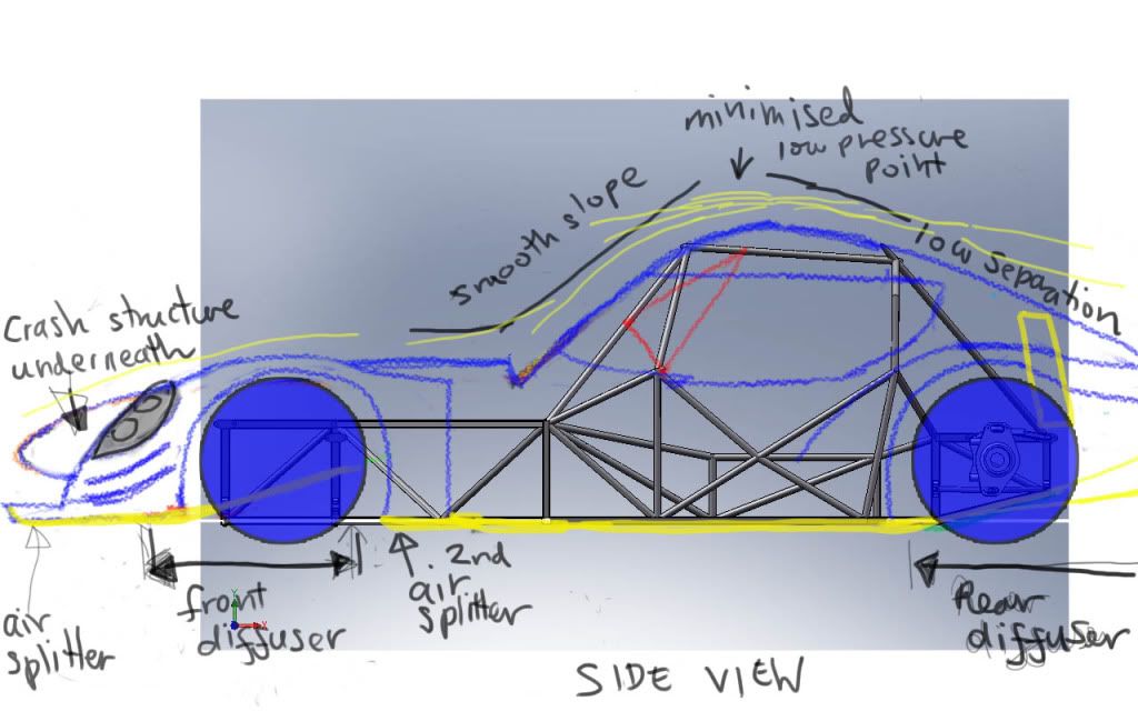
I thought about that. The whole bell crank, push-rod and shocks are in a single plane, so when the suspension moves all the loads are in that plane just as if it were arranged in a vertical position. The effort was also made to put the line of action of the push-rod and shock close to a tangent around the bell crank. I have to post a picture of how I did it. Additionally i will get a picture of the reaction force vectors from the motion simulation to show you. (just the directions, not the magnitude because the proper forces were not put in yet)

Overall it was inspired from the Lemans cars. Something like on this page http://www.mulsannescorner.com/couragec65-4.html

The wheel movement, I don't know how much the car will experience but i chose about a max 2 inches up and 2 inches down. It does not max out the shock's extension or produce extreme bell crank rotation. Then again i have no no clue what is a good rotation range for a bell crank until i run it in the motion simulation.

The relation between the diffusers and the control arm length/chassis width? I read that the Acura ARX 02 had rear wheel sized tyres on the front and they ran into the problem of limited front diffuser area because there is a regulation that says the chassis (the area between the front wheels) has to have a minimum width at the front. To solve the problem Wirth Research had to design the car as with a zero keel and raised nose configuration. This enabled the front diffuser exit to go straight across the underside of the car from wheel to wheel, providing a bigger exit. In my case I cannot raise the front of the car but I can change the width of the chassis between the wheels to maximise the front diffuser area.

http://www.mulsannescorner.com/AcuraARX-02-1a.html

This was the original concept I had, a lot has been changed though:

Image
πŸ–οΈβœŒοΈβ˜οΈπŸ‘€πŸ‘ŒβœοΈπŸŽπŸ†πŸ™

Racing Green in 2028