ringo wrote:I drew a 2 element wing and ran it at 90m/s; over 200mph. This wing is my creation, it may as well be rubbish


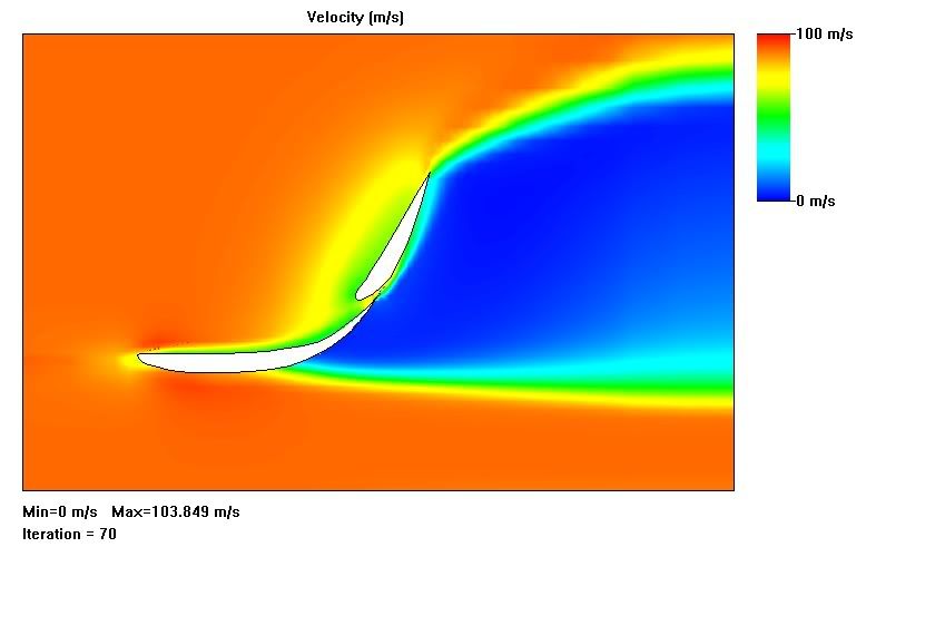
^^Standard wing, no blown flap. this is velocity not pressure, (do not use this to visually determine where the high pressure is, there are density changes as well.)

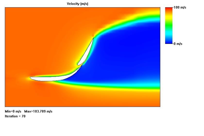
^^tangential blowing.
observations, blowing tangential to the 2nd element surface, 90m/s 1atm.
1) no effect on top of main element, though slot is less choked. The separation point is move slightly backward beneath mean element.
2) no major difference to boundary layer, maybe reduces it's thickness which is very minsicule.
3) Slight difference in velocity gradient near trailing edge, and has a pull on the air on the front side of 2nd element, changing velocity gradient there as well.
4) wake is unchange.
What I observed is that, blowing at the second element does little to change the wing performance. Reason being the velocity is already high on the elements surface,and there is no danger of separation because of the strong up-wash coming through the slot.
I also observed that the boundary layer seemed to be quite small, which is good. No major differences though.
From observing the existing flap blown planes, flap blowing is best done in the slot. Having it at the middle of the second element is just in the wrong place. It would do well in the slot or on the bottom of the first element. It is also meant for blunt thick trailing edges where separation occur, such as in the pocket of a wing where the flap retracts in.
So with the understanding that blowing tangentially to the elements surface is redundant because the boundary layer is already highly energized; I angled the blowing away from the surface.

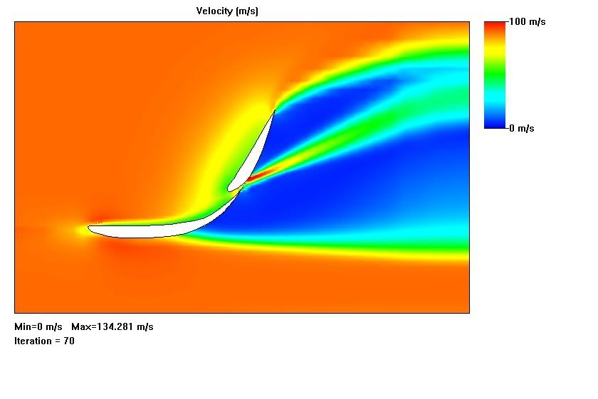
^^blowing at an angle
This of course "stalled"?? the element leaving a detached boundary layer on the back side of the element.
observations for blowing at and angle at 90m/s, 1atm. and 373k :
1) Though the air jet was at free stream pressure, it quickly diffused to the local pressure immediately behind the wing.
2) The off shot jet was diverting the flow from off the wing and out into the wake. leaving a stalled area on the element surface downstream of the jet.
3)The wake was being noticeably distorted by the jet.
What i realized from this is the fact that the element stalled has little to do with the total outcome on the drag. The stalling takes place in the wake because of the almost vertical element. It does not increase the size or height of the wake.
This is slightly different than an aircraft, where the wake is slightly behind and stalling of the top surface can increase the wake size.
The whole point is not realy stalling the wing. Stalling is part of it. I think the bigger picture is
passive wake control. The angle of upwash from the wing is virtually an extention of it's angle of attack. The up wash is also connected to the wake. If the up wash is pulled in, it will virtually reduce the AOA and the drag. Varying jet speeds will pull on the wake with varying strength.
This slot more than likely jets air outward from the element into the wake and distorting it, maybe that is why we saw that gap in the flow vis, the flow shot off into the wake.
I got some results, which could be completely off because of the size of the computational domain that i use. My PC crashed a couple times looking for the right level of detail.
The reductions in down-force were very small, and reduction in drag was also small.The made up wing has a L/D ratio of 0.9148 .
from normal flap to blowing tangentially: Lift/Drag ratio 0.91566 ,.32% drag reduction, .229% DF reduction
from normal flap to blowing into the wake: L/D 0.9128, .5% drag reduction, 0.71% DF reduction
And remember my wing profiles are made up!, this is not a true reprsentation! 
These numbers and opinions are also to be taken with a grain of salt!!! I jut put them there to give an idea of the scale of the improvements. 


