- Login or Register
No account yet? Sign up
[-X , remember regulation states the construction must be rigid with no relative degree of freedum to the sprung mass. Hoses with air affecting the aerodynamics are clear violation. The inspectors would just rip them out.Pup wrote:Here's one way this could work:n smikle wrote:When I imagine the construction of the knee activator, with no moving or flexible parts, I can only see a solution with a hollowed out wall or some hollow duct in the side of the chassis with a hole in it.
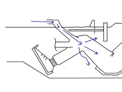
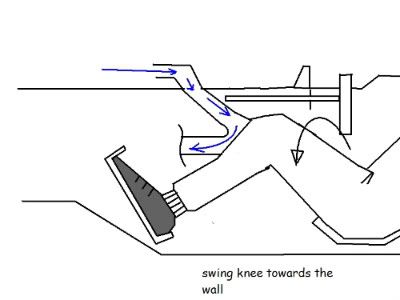
The driver puts his knee over/in the hole to activate it (driver activated device). A problem is that the driver might not seal the hole properly with the side of his knee. Then again this depends on what you want to happen in the duct. If you want to stop air loss in the duct, then the drivers knee must seal the hole. If you want to decrease airflow in the duct the drivers knee only has to go inside the hole, into the ducting to block off most of the flow. Just some thoughts. Not saying it can not work even though it seems illegal anyway..but I think the air can be controlled without the driver and the weird ducting. (we still have to establish if the air int he duct is powerful enough to divert the bigger flow).
From scarbsf1
Imagine making a duct for this in the side of the chassis... I don't know.. I have to think hard on it.
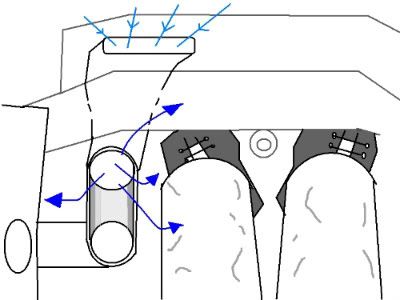
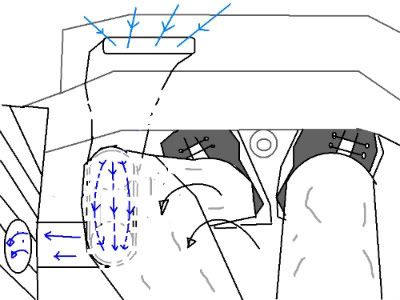
You see that the scoop is split into two chambers. Also remember in the diagram of the fluidic valve that there are two control points. Add pressure to one or the other, and the main flow switches sides. I've been reading up on fluidics a bit, and I gather that the control can be either a continuous stream of air, or it can just be a puff one way of the other, and the main flow will swap sides and remain stable until you 'puff' it the other way.
OK, so if the scoop has two chambers, imagine two flexible hoses then running from the scoop to the rear of the car, connected to the fluidic valve. Now imagine that the hoses are pliable enough that the driver could easily cut off the flow off of one by pressing his knee against it - pinching it closed. Since cutting off the flow of one is equivalent to increasing the pressure of the other, you could effectively switch the main flow back and forth by pinching one hose or the other. Or, if there needed to be a default state, perhaps it could be set up so that the driver would need to maintain pressure on one of the hoses to keep the flow switched.
I'd think this would be a tricky thing for the driver to do, but I figure I'd throw it out there for the sake of conversation. I do think this would be easier to accomplish than having the driver try to cover some hole with his knee. Personally, however, I still think there would be a way for this to all be done without driver input.
The image you linked to doesn't show the inlet. And I think the previous image shows the inlet blocked by a piece of carbon AND split vertically.ringo wrote:The inlet is not split, it's actually blocked half way with a piece of Carbon.
They were probably testing if they could reduce the opening area. When they found out they could they then changed it to the smaller opening here:
http://f1.gpupdate.net/en/photolarge.ph ... 8&catID=10
There's no need for it to be at the nose. Imagine all the piping losses etc.myurr wrote:If the snorkel is related to the fin then it would be a passive system - the fluidic valve that has been discussed is very interesting and I'd imagine the most likely system. The snorkel could simply be carefully tuned so that upon reaching a certain pressure - ie. speed - it activates the fluidic switch, enabling the stalling of the rear wing. The car slows below that speed and the pressure reduces and the switch returns to its default state.

Sorry about that, I now see the vertical split.volarchico wrote:The image you linked to doesn't show the inlet. And I think the previous image shows the inlet blocked by a piece of carbon AND split vertically.ringo wrote:The inlet is not split, it's actually blocked half way with a piece of Carbon.
They were probably testing if they could reduce the opening area. When they found out they could they then changed it to the smaller opening here:
http://f1.gpupdate.net/en/photolarge.ph ... 8&catID=10


Same, it has nothing to do with it, its obviously to cool something else.FGD wrote:I'm having a very hard time believing this little inlet has anything to do with the rear wing. The most obvious purpose, in my mind, would be that they've got a hot spot within the cockpit that needed some cooling.
+1, this thing is to small to produce an airstream to the rearwing, the airbox channel idea is more likely used...djos wrote:Same, it has nothing to do with it, its obviously to cool something else.FGD wrote:I'm having a very hard time believing this little inlet has anything to do with the rear wing. The most obvious purpose, in my mind, would be that they've got a hot spot within the cockpit that needed some cooling.