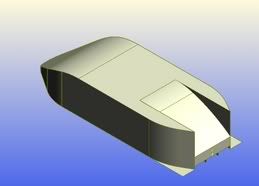
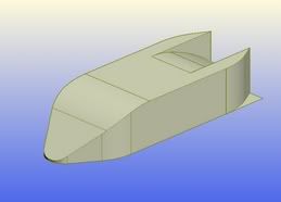
Formula 35!

Please discuss here all your remarks and pose your questions about all racing series, except Formula One. Both technical and other questions about GP2, Touring cars, IRL, LMS, ...
User avatar
greenpower dude reloaded
6
Joined: 29 Dec 2005, 20:03
Location: Portsmouth, UK

Formula 35!

Post

Ok so it doesn't have the same ring to it as F1, WRC or GP2 nor is it anywhere near as fast as those previously mentioned but F35 is a project im puttin a lot of time into.

Basically every team is givin a 600watt 24v Motor tht spins at 2800rpm. now you would be forgivin for thinkin tht a vehicle with such power source is only going trundle along at electric wheelchair speeds but tht probably couldn't be more from the truth as i belive i could build 1 capable of 60mph however it may have to be slightly under geared so as not to run down the batteries too much because this is after all a 6hr race. i've so far got most of the chassis materials (pultruded carbon fibre tube for the suspension, Aerolam for the main body of the chassis and fibreglass box section for the roll bar and front crash structure) the plan is to get the overall weight below 40kgs minus batteries and driver.

but i've created this Topic so that i can seek your advice on aerodynamics i currently have a pretty good understanding of low speed aerodynamics and plan to do testing once the car is up and running however im planing on building the mk1 for under £1500 and due to time restrictions im planning on creating a plywood/foam bodywork for the Mk1.

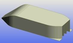
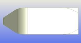
I'd appreciate it if u tell me what u think of this idea the wheels aren't shown but they'll be internal and i'll run it sumwhere between 30-50mm ground clearance. The driver is almost laying down inside. its 1000mm wide by 500mm high

Image
Front
Image
Trimetric
Image
Plan
Image
Underneath

manchild
manchild
12
Joined: 03 Jun 2005, 10:54

Post

At first I spotted the huge diffuser at the back which is no good for aerodynamic efficiency because your car isn't supposed to go fast trough corners. Less square cross section would give better results but streamlining will increase costs. I think that you should search for inspiration among solar powered racers…

User avatar
greenpower dude reloaded
6
Joined: 29 Dec 2005, 20:03
Location: Portsmouth, UK

Post

yeah the diffuser was actually a concern of mine because i was tryin to create sumthin like that so that it would relive any vacuums formed at the rear which would remain vacuums had i have just gone for a flat cut off. obviously over time i plan to make it more streemlined but with only plywood available to me at this moment in time i dont think i could do too much better. i did design the diffuser to have a slight curve at the top to try and bring the air out a tad more horizontal. i dont think i could get the rear any narrower as that is pretty much maximum it can be long (2800mm) and i don't think i could make the car narrower than a meter when you consider that this car must have suspension.

...and yes it would still create downforce but im not sure tht a diffuser creates too much drag please correct me if i am wrong but i always thought that a diffuser increased downforce by reducing upthrust. but i maybe wrong i am still relatively new to all of this having only spent jus 5yrs involved in small vehicles similar to this.

i don't think a solar car would b too good for inspiration as they are a compromise and usually have stupidly high groundclearance and therefore a rather high CG plus they usually have a very large SA which is perfect for catchin the sun but not too great for laminar flow.

but like i said please correct me if im wrong im only 17 so im still learning :D

manchild
manchild
12
Joined: 03 Jun 2005, 10:54

Post

I think that the problem with your diffuser is its size. The amount of air that gets below the car is much smaller than flow suitable for such diffuser and that is it would cause vacuum behind the car and turbulence and drag as result of it. In a way your car has rear end similar to station wagon or hatchback

Last shape in the pic in this link “streamlined Half-body” is something you should look for http://www.f1technical.net/articles/10

Image

User avatar
greenpower dude reloaded
6
Joined: 29 Dec 2005, 20:03
Location: Portsmouth, UK

Post

the strem lined half body was something i have been trying to keep in mind since day one but ideally i would like something a little bit more balanced heres another idea i just created after thinking more about what you said Image

DaveKillens
DaveKillens
34
Joined: 20 Jan 2005, 04:02

Post

One HP = 647 watts. So you have almost one HP to play with.
I too would suggest you look at the solar racers in their areo use, since you would be running at comparable speeds. The idea is to have a very smooth surface where the air does not experience any sudden changes that could generate turbulence. If you have turbulence, it is power being robbed from the powerplant. A squared cut tail and diffusers are great for managing air and downforce, but you are looking for just pure low aero drag. So please, clean up the tail and give it a smooth transition from the general bodywork to a pointed tail. In fact, you would find improvement if you copied the nose to the tail, making each end similar.
As an electician I'm concerned about the electrics. Most times, an electric motor is designed to run at maximum efficiency at just one voltage and RPM. Going to a higher or lower RPM or voltage could reduce efficiency. Many people assume that if you run an electic motor at voltages less than suggested would result in less electical consumption. But in fact, it almost always results in a less efficient motor that runs hotter than planned. Also, there is a very good chance that running such a motor would result in it getting hot. And if it gets hot, then efficiency drops and electrical consumption skyrockets. It may be advantageous to use something like a bicycle chain derailleur and gears to keep motor RPM at optimal level. In fact, I suggest you consider the strategy of running, then coasting, and so on. You will probably be the fastest device in the last half of the race.
This race is probably all about battery management, more than anything else.

User avatar
greenpower dude reloaded
6
Joined: 29 Dec 2005, 20:03
Location: Portsmouth, UK

Post

mimicing the front is another idea i have actually been playing with and the plan is to make sections of the bodywork interchangeable so that i can test and see which is the best however the problem is space and the fact that the rear wheels have to be as far back as the wheel housing you can see poking out of the back and tht is at the max allowed dimension of 2800mm.

I can understand what your saying about the motor gearing etc but i must apologise for not explaining everything properly. Basically im goin to run it slightly under so as not to run down a set of batteries too much over 1hr 30 until the next set come on. you are givin 3 sets of 2 12v Car batteries that can be charged at anytime during the race however you can only charge one set at a time. i will also be using a 7 speed Shimano Nexus internal gear hub although marginally less efficient than a derailleur they are far more reliable as we have found that a derailleur tends to cause more trouble than its worth and takes up far more space and im not sure about coasting and burning with the throttle we have always found that you will only do the motor damage that way as you will send a surge to the motor when u do that, however I would be grateful if you could give me some advice on the electronics. I have made the descision to run an On/Off System rather than one with a speed controller as these have also been found to be rather problematic. If you have a look at http://www.greenpower.co.uk/design.htm you will find information on the rules, the motor curve and further info.

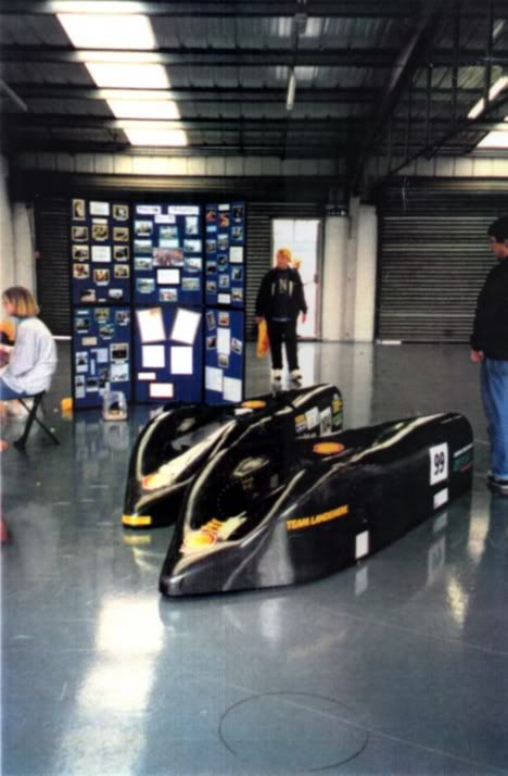
Back to aerodynamics for a second i'm still not sure on the idea of making a car similar to a solar car because they are totally wrong for a series like this. they are too high up so that the wheels don't spoil the the surface area if you were to bring the the body down and had the wheel housing poke out of the top more like a classic land speed record car but then that means i would have to start thinkin about fibreglass or prefrably carbon fibre which my budget just can't stretch to for the coming season. below is a pic of two other cars i spent a few years working on back in secondary school for the shell mileage marathon we won various awards for these and manage to get in excess of 3800mpg with these the plan is to eventually get my car more like these however these have 3wheels where as i have four making it far more difficult.

.....but tht doesn't make it impossible.
Image

Guest
Guest
0

Post

I'm impressed.
When you examine an electric motor purely from a wiring perspective, it's basically a very long wire that runs a complex path through a controller, armatures, windings, and back out. If you measure it with an ohmeter, and do the simple Ohm's law to calculate resistance with voltage to calculate, you will find that the amperage is much higher than wanted. But when the motor is running, it's not drawing that much amperage. That's because when the motor is rotating, the interaction between the stator and rotor create what is called CEMF (counter electromotive force) that , in layman's terms, pushes back against the current. That is why, if you hook up an ammeter to a motor during startup, a huge spike of amperage blasts down the wires, then diminishes as the motor RPM's climb. Some electic motors have a device that is basically a resistor in line with the motor, and once certain RPM is reached, it is disconnected from the circuit. It's a system to add a lot of electrical resistance to the electric circuit to keep the inrush of amperage to a level that doesn't fry the motor.
Electric motors are designed to withstand the hardships of startup, though. But there is heat accumulation during the startup phase. If you execute the startup cycle repeatedly and for an extended period of time (which was the strategy I was supporting) heat buildup could damage the motor. For example, one high performance electric motor used for aircraft engine startup was limited to just three startup attempts per half hour. In other words, if we didn't give that motor at least ten minutes to cool off, it was liable to heat damage.
Now that I'm aware that you have more than one battery to play with, it's obvious you're the expert on determining the battery use strategy. The strategy will determine what kind of motor controller you will use.
As far as the aero, having to fix the location of the rear wheels hampers design parameters. On your third post you posted a pic of an alternative design with some of the rear bodywork coming down to meet the rear diffuser. Why not start it sooner forward, and have it drop to the rear, al the way to the bottom of the bodywork? keep the rear vertical portions ( I assume that's where the rear wheels go).

[/img]

User avatar
greenpower dude reloaded
6
Joined: 29 Dec 2005, 20:03
Location: Portsmouth, UK

Post

I've just finished some more designs which i will post later tonight which show a far more developed design with a diffuser that is 1deg bigger at the back than at the front nose cone. plus i have included two wake infill tubes that pick up air about 300mm infront of the rear wheels which then run over the motor to help cool the motor and run straight out of the back.
The curve comes down further at the back but comes to cut off which the brake lights, indicators and the wake infill ventillation.

User avatar
greenpower dude reloaded
6
Joined: 29 Dec 2005, 20:03
Location: Portsmouth, UK

Post

Well.. sorry for the delay!! but here they are!
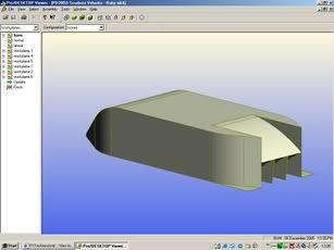
Heres the picture your probably most intersted in;
Image
Rear this shows off the 2 Wake Infill holes at the moment im not sure whether I should keep them stacked on top of each other like tht or seperate them a bit and make them horizontally parallel.

Image
And this shows off the cooling/wake infill ducts.

Image
now finally here is the new nose cone only a minor change really but should make a +ve difference.

let me know what you all think!

- Luke

manchild
manchild
12
Joined: 03 Jun 2005, 10:54

Post

Having in mind materials you are forced to use for bodywork this design now seams to be ok. If it is no problem, you could loose that vertical rear end plate and let top fall down all the way to bottom.

Perhaps you should also reconsider position of engine air cooling inlets because if they pick the air from below than there is much more chance for dirt to get in, especially if you face dust, mud or rain. Anyway, I have no idea on which surface this vehicle will be used.

User avatar
greenpower dude reloaded
6
Joined: 29 Dec 2005, 20:03
Location: Portsmouth, UK

Post

yeah i thought about that but i can't bring the begining of the curve any further forward and i don't want to make it too steep. Plus the reason i kept the diffuser was to do with a conversation i had with John McNeil of Team Nasamax (the LeMans team that ran on bio ethanol) nd he recommended a 1deg change.

The car will race on proper tracks such as Castle Coombe, Thruxton, Goodwood and possibly the Ford Dunton Test Track. so they're not likely to be too dusty or too dirty and as for rain if its wet the water would actually provide additional cooling but thanks for your concern anyway.

DaveKillens
DaveKillens
34
Joined: 20 Jan 2005, 04:02

Post

I believe this redesign would have less drag. There are very few places where the air would experience sudden changes in direction or where turbulence would be generated. For ducting, have you considered NACA ducts? They have low drag, and deal with boundary layer air. Maybe even mount them on the sides, instead of top. That would allow the top to be removable, and simplify maintenance, maybe even battery changes.
On the upper corners, have you considered less sharp corners? If rounded, the air that would migrate from top to side (or vice versa) would not have to expereince the sharp corner (more turbulence). On the pictures of the vehicles for the Shell vehicle management, the corners are rounded, as I suggest.
At the tail, between the rear "roof" and diffuser you still have a vertical plate (viewed from the rear). I believe you have to have a spot to mount lights and such, but why not also incorporate the air exhaust there too? Or have the top surface drop all the way to the bottom, have flat surface on the rear of the rear "fins", and mount the holes and required equipment there? That way, the rear wheels could be placed almost at the very rear of the vehicle.

manchild
manchild
12
Joined: 03 Jun 2005, 10:54

Post

I was thinking to suggest NACA ducts but I wasn't sure would it be easy to make them easily with material he has to use for bodywork.

http://home.hiwaay.net/~langford/nacadu ... A_duct.jpg

User avatar
greenpower dude reloaded
6
Joined: 29 Dec 2005, 20:03
Location: Portsmouth, UK

Post

The rear verticle plate is where i have placed the air exhuasts which although not easy to see are there on the design i posted a few days ago and the current ducts are actually underneath allowing the top to be removed for battery/driver changes but this is good because it shows we are all thinking along the same lines.

I am now reseaching NACA ducts and they look perfect for what i need so im gonna try and use them for the cooling.

I'm now planning to try and keep the rear pretty much how it is now unless anybody else has any suggestions. I like your Idea dave however I don't want to have the wheels to far back plus the actual width of them is relatively nothing as the tyres are only about 15-20mm wide slicks so keeping the rear wheel housing like it is should be fine.

I'd still like to hear everyones suggestions about the overall shape but the next aerodynamic part to take into consideration are the wing mirrors now these can be vacuum formed as i have acess to a small vacuum former. I've considered the half teardrop but there would almost deffinitley be some distortion which i'm not too keen on from a safety point of veiw.
I will post a few ideas on here soon.

another small aerodynamic wingmirror consideration is whether to place them on the top or on the side because the vehicle will have a windscreen that'll stretch from just behind the front nosecone (300mm long) to the rear roll bar (2100mm away from the front of the nose cone) but it will also have a window either side of the driver.

Thanks for your help guys,

- Luke