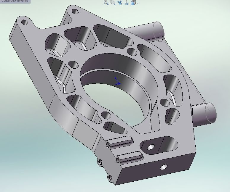
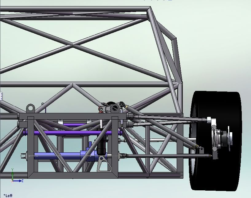
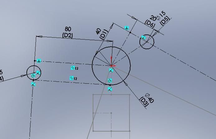
Well here is the sketch of the part in orthographic view.
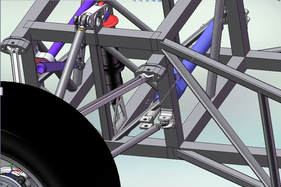
The largest circle is the centre of the bell crank.. the circle ont he right where the push rod bearing is.
You can see the point to the left "20" on the dotted line of action is where the 90* point is and to the right is the off-set point.
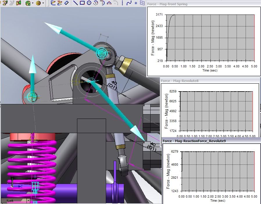
This is the test with it at 90 degrees. A constant force of 4000N is applied to the lower control arm. The the top graph is the force in the spring. THe middle graph is the magnitude of the force in the bell crank bearing. The lowest graph is the force on the push-rod bearing. (The crank has rotated past the initial position).
Next is the test with the 20mm offset. Remember the crank has rotated past the initial position:
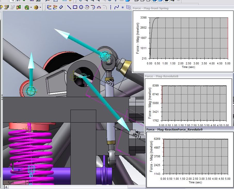
The results are interesting because the 90 degree setup needs a longer push-rod and the offset setup a shorter push-rod for everything to fit. (remember ignore the other parts like the linkage they were not modified for the simulation I just changed the bell crank and push-rod)..
We see that the 90* setup has a smaller force magnitude in the both the spring and the Bell crank bearing. But a higher force in the push-rod.
The offset arm has a higher force in the spring and bell crank bearing but a lower force in the push-rod: ~2 lbs force less. On the other hand more force was put into the spring ~ 40 lbs at the expense of putting more force in the bell crank bearing ~ 40 lbs too. this is reasonable since it is approaching closer to 90.
I think I should change the behaviour of the force to something else to get better graphs. The input force was also not enough to produce the maximum wheel travel. We need a clearer picture.. but so far it seems the differences are on the order of 10N to 200N with this 4000N force input (900lbs), the differences in imperial are about 2 lbs to 44 lbs difference in the respective parts.. which is very small. Maybe a graph of force compared with the upward movement of the wheel?
But as you can see the space efficiency of the offset bell crank was the major reason why I changed to it. A bigger radius could prevent binding in the 90 degree setup but it just depends on how large the user wants the bellcrank. Maybe a different bell crank radius for the 90 would make it closer but we need to keep things constant for comparison. So radius for radius the offset will have more force in the spring (approaches 90 as it rotates up) but a detriment of more force in the bearing.
**IT is still not clear the shape of the graphs which is more important..whether progressive or not As mep says, i think the 90 one is going to get relatively harder as the suspension moves up. but I want to a graph to compare the progressiveness of each one setup. I will get back with this..
Anyway some other cars use it too.. but this one is a more extreme example.
http://www.ultimatecarpage.com/pic/3824 ... 1b_11.html


