How is the engine/gearbox assembly mounted to the tub?

All that has to do with the power train, gearbox, clutch, fuels and lubricants, etc. Generally the mechanical side of Formula One.
User avatar
ringo
230
Joined: 29 Mar 2009, 10:57

Re: How is the engine/gearbox assembly mounted to the tub?

Post

xpensive wrote:
ringo wrote: ...
Therefore the bolt/pin, has to be designed for to take that stress since deflection is not possible.
The above is a good xample marcush, when I hear things like that from my PrE-designers, I politely ask them to quantify the load and stress introduced in the bolts in order to keep an engine-block from xpanding when going from 20 to 120C?

No you are misunderstanding me, maybe you are not visualizing carefully and stereotyping. I am fortunate enough to not be taught engineering on a CAD program.
I use them now but i don't depend on them.

That is why i asked all of you to put up diagrams, it's easy to misunderstand all the jargon.

If you read what i said carefully, you will see that i never said the engine cannot expand. I said that the bolts do not deflect. It's not possible. And i am not going of a CAD visual representation.

Would you like to see why with a diagram? :wink:
For Sure!!

Richard
Richard
Moderator
Joined: 15 Apr 2009, 14:41
Location: UK

Re: How is the engine/gearbox assembly mounted to the tub?

Post

xpensive wrote:
ringo wrote: ...
Therefore the bolt/pin, has to be designed for to take that stress since deflection is not possible.
The above is a good xample marcush, when I hear things like that from my PrE-designers, I politely ask them to quantify the load and stress introduced in the bolts in order to keep an engine-block from xpanding when going from 20 to 120C?
I'm impressed you ask them without laughing.

User avatar
ringo
230
Joined: 29 Mar 2009, 10:57

Re: How is the engine/gearbox assembly mounted to the tub?

Post

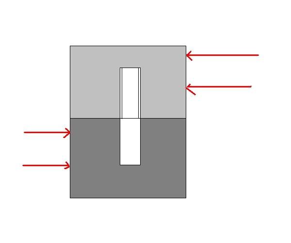
can this bolt bend?
It is set at both ends, one part moving relative to the other. The movement could be from thermal expansion.

Image

It cannot bend, There are no free ends. It can only shear.
If there is any bendint at all, then the threaded hole may have slight distortions, but this should be microscopic since thermal epansion would shrink the bolt hole.

Can you appreciate what i was saying?

There is no way possible to design for movement, Unless you want the hard points to move themselves and that's counter intuitive. Hard points restrict movement. The bolt simply has to take the shear stress.
A bolt size has to be chosen that can take the expansion stress of the engine, due to relative motion between the bulkhead and the engine since the thermal stress is in the shear plane alone. Agree?


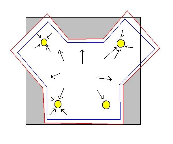
There is a radial outward push on the bolt diameter in the shear plane however.
Image

Engine growth from thermal expan in red. Black arrows represent direction of expansion. This is in the shear plane at the interface of engine and monocoque.

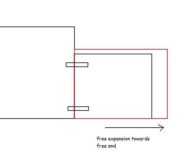
Thirdly, in regards to axial stress on the bolts, as i said earlier, one end of the engine is free to expand, so the bolts wont be under tensile stress. I guess there will be a slight compressive stress on the threads since the bolt holes are shrinking.
Image

diagrams are important.
Last edited by ringo on 22 Nov 2010, 19:52, edited 1 time in total.
For Sure!!

User avatar
747heavy
24
Joined: 06 Jul 2010, 21:45

Re: How is the engine/gearbox assembly mounted to the tub?

Post

marcush. wrote: 747h ...I waited for this question to come really and it had to be asked by you really =D> and I do admit not to have the explanation.
Hi Marcus,
Do I take it as a compliment, or as an indication, that I´m annoying you?
I hope the later is not the case,if so I appologize for it.

Now, I will readly admit, that this is far from my field of expertice, and that I´m not the best person to comment on it, from a in deep engineering level.
Others such as Riff_Raff are maybe in a better position to do so.

From a practical expirience level, I can say that aluminium alloy inserts/hardpoints are common in motor racing monocoques, but I agree with Riff_Raff that Titanium inserts would have a better ETC match, and maybe this is the reason, that you see now more Titan/CFC hybrid gearboxes then Aluminium Alloy/CFC ones.
AFIAK - Invar would be the metal with the closed CTE to CFC, not sure if it is used somewhere.

Fibre pre-strech during curing, could/would be a way to reduce stress in the hybrid structure for a choosen temperature range.

I can see, that this (difference in CTE) could have contricuted to the problems of Steward GP.
But it´s pure speculation, as I have Zero knowledge about this application.

I do know, that Ti alloys are the material of choice for components such as flextures or sperical bearing carriers in wishbones and push rods.

A aluminium alloy-CFC combo has other problematic characteristic as well, it´s prone to galvanic corrosion under some conditions, for this reason the carbon and the aluminium are normally seperated by a layer of glass scrim in the laminate for certain applications, especially if a fastener(3rd material),such as a bolt or rivet, can form a circuit with fibre contact. (offshore industry, sailing in salt water etc.)

I dont know for sure, what the hardpoints in an F1 tube are made of, it has been said in some publications to be aluminium alloys.
I know for sure that these parts in an DTM survival cell structure are aluminium alloy.
And yes, delamination on these parts is a problem, and supension and engine hardpoints in an LeMans monocoque/tub are ND (ultra sonic) tested in regular intervalls, at least in the applications I´m familar with.
(I guess Peugeot will know something about it, as well :wink: )

While not 100% related to the topic, this may gives a glimpse of the use of hybrid materials in the aerospace industry.
COMPOSITE MATERIALS FOR AIRCRAFT STRUCTURES wrote:
Hybrid Metal/PMC Composites

Structural metals, such as aluminum alloys and composites, including carbon/
epoxy, have a variety of advantages and disadvantages for airframe applications. For example, metals are prone to fatigue cracking but PMCs are not; PMCs are easily
damaged by low-energy mechanical impacts but metals are not. Thus, the potential
exists to combine these materials in such a way as to get the best of both materials.
One such approach is the aluminum/fiber composite hybrid laminate, 13 which
consists of thin sheets of aluminum alloy bonded with a fiber-reinforced
adhesive. When a crack grows through the metal, the fibers, which are highly
resistant to fatigue damage, are left spanning or bridging the crack in its wake
(Fig. 1.7). The result is a reduction in crack growth rate by approximately
one order of magnitude and an insensitivity to crack length. However, the fibers
have little influence on crack initiation and, indeed, because the hybrid composite
has relatively low modulus, the increased strain in the aluminum alloy can
encourage earlier crack initiation. The fibers also significantly increase the postyieldstrength compared with unreinforced aluminum alloy, and the composite has a much higher damping capacity.
Disadvantages of these materials include sensitivity to blunt notches due to the
inability of the fibers to withstand very high strain levels. Thus, the notch
insensitivity of metals is not retained in the hybrid. Also, depending on the
reinforcement used, the elastic modulus of the hybrid is generally lower than
aluminum alloys, however, this is compensated for by a reduction of specific
gravity of between 10-15%. Another problem is cost, which is typically 7-10
times that of standard aerospace-grade aluminum alloys.
The aluminum alloy is generally either 2024 T3 or 7475 T761, 0.2-0.4 mm
thick. The composite is aramid (Kevlar) or glass fibers in an epoxy nitrile
adhesive, around 0.2 mm thick for unidirectional reinforcement, or 0.25-0.35 mm
thick for (glass reinforcement only) cross-ply. With aramid reinforcement, the
laminate is called ARALL (aramid reinforced aluminum laminate), and with
glass fiber, GLARE. Because of the sensitivity of aramid fibers to compressive
stresses and the favorable residual strength that is produced, ARALL may be
pre-stretched. This also overcomes, at a cost, the adverse residual stresses arising from the differences in thermal expansion coefficient between aramid, or glass, and aluminum. GLARE does not require pre-stretching as the high-strain glass
fiber used is less susceptible to compressive stresses. Consequently, the glass
fibers can be cross-plied to give crack growth resistance in two orthogonal
directions as may be required for a fuselage structure. Although GLARE has a
lower modulus than conventional aluminum alloys, with a reduction of around
20% (particularly with cross-plied fibers), it has the best resistance to fatigue
crack growth.
Significant weight savings--20% or so---can be achieved in fatigue-prone
regions such as pressurized fuselage skins and stiffeners and lower wing skins by
the use of these materials. The hybrid composites are also suited to high-impact
regions such as leading edges and inboard flaps and to components subject to
mishandling, such as doors.
For applications requiring higher stiffness and strength, as well as a higher
temperature, capability studies have been conducted 13 on hybrid laminates made
of thin sheets of titanium alloy (Ti-6A1-4V) and a low-modulus carbon fiber
composite. The matrix for the composite and adhesive is a thermoplastic (PEEK).
This laminate is reported to have excellent resistance to fatigue crack growth as
well as good blunt-notch strength.

Image
"Make the suspension adjustable and they will adjust it wrong ......
look what they can do to a carburetor in just a few moments of stupidity with a screwdriver."
- Colin Chapman

“Simplicity is the ultimate sophistication.” - Leonardo da Vinci

User avatar
ringo
230
Joined: 29 Mar 2009, 10:57

Re: How is the engine/gearbox assembly mounted to the tub?

Post

richard_leeds wrote:
xpensive wrote:
ringo wrote: ...
Therefore the bolt/pin, has to be designed for to take that stress since deflection is not possible.
The above is a good xample marcush, when I hear things like that from my PrE-designers, I politely ask them to quantify the load and stress introduced in the bolts in order to keep an engine-block from xpanding when going from 20 to 120C?
I'm impressed you ask them without laughing.
Ignorance is bliss eh?

:lol:
If i had known they were referring to me, i would have put them in their place from the beginning? :wink:

The tables have turned now, lets wait for the responses.
i often say that when you can measure what you are speaking about, and express it in numbers, you know something about it; but when you cannot measure it, when you cannot express it in numbers, your knowledge is of a meagre and unsatisfactory kind.

Lord Kelvin
Not to say these guys don't know what they are talking about, but sometimes words alone can be deceptive. You'd be hard pressed to think who knows what they are talking about.
For Sure!!

User avatar
ringo
230
Joined: 29 Mar 2009, 10:57

Re: How is the engine/gearbox assembly mounted to the tub?

Post

The next step is a sample calculation, no cad, just some equations to quantify the stress on a bolt pattern with given material properties and diameter under stress from an expanding engine. Who stepping up to the plate? 8)
For Sure!!

User avatar
747heavy
24
Joined: 06 Jul 2010, 21:45

Re: How is the engine/gearbox assembly mounted to the tub?

Post

Thanks for putting up the drawings Ringo.
Beeing a bit lazy, I "borrowed" one of them - I hope you don´t mind.

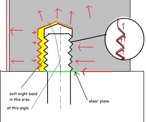
What about this case?

Image

This is what I had in mind, and maybe Xpensive as well.
What if the bolt is not in contact at the full length of the bore, just on the far end. IMHO the engine could overcome the friction and move slightly, by doing so bending the bolt ( the green line indicates the centre line of the bolt in the bend state). This was, while I wanted to use a sperical bearing (orange) at the end, and
I thought (maybe wrongly) that this was where X wanted his sperical nut surface.

Just my two cents
"Make the suspension adjustable and they will adjust it wrong ......
look what they can do to a carburetor in just a few moments of stupidity with a screwdriver."
- Colin Chapman

“Simplicity is the ultimate sophistication.” - Leonardo da Vinci

xpensive
xpensive
214
Joined: 22 Nov 2008, 18:06
Location: Somewhere in Scandinavia

Re: How is the engine/gearbox assembly mounted to the tub?

Post

I'm at a bit of a loss here as where to begin actually, but this is how I would try to xplain it to my ProE-brats;

- Imagine you have a 400 mm long, 50 mm diameter Alu-bar, you heat it up 110 K to watch it grow one full mm.
- Put the bar in a hydraulic vice to compress it to its original length, you succeed with that, but at what force?
- Hooke will tell you that stress is epsilon times modulus, epsilon is 1/400 and E is 70 GPa, resulting in 175 MPa.
- 175 MPa over the area of a 50 mm dia bar equals 344 kN or about 35 metric tons, which would shear off an M24.

Having said that, if I would catch anyone in my office even considering installing a bolt in a shear-loaded position,
he or she be long gone before lunch.

@jumbo; That's how you typically install a bolt, with a clearance to avoid shear-forces. A bolt subjected to shear is simply not a bolt any more, but a dowel-pin perhaps? The spherical seat is a trick you use when you xpect lateral movement.
"I spent most of my money on wine and women...I wasted the rest"

User avatar
ringo
230
Joined: 29 Mar 2009, 10:57

Re: How is the engine/gearbox assembly mounted to the tub?

Post

I don't get what you mean by a bolt subjected to shear is not a bolt any more?
I guess it depends on the words being used, dowell, bolt, stud.
But a bolt can still be subjected to shear. It's not ideal application but it happens, especially in our case.

I get your example with the vice, but that restriction to thermal expansion is in the axial direction, along the length.
In the case of the engine block and the bolt, the lengthwise direction is free to expand, but it is the radial diretion that will be highly resisted.

What you said holds some weight on the bolt threads level, in terms of the bolt expansion and engine block expansion. 747 was alluding to this. But i think that is more of a bolt torque issue than a design issue with the hard point insert.

The bolts could be torqued much higher on installation, to compensate for the expansion of the hole when the engine gets hot. But in regards to movement at the interface, i don't think the bolt will move there.
I stand corrected on one slight detail. There will be deflection in the expanded hole, but this is probably on the level of thousandths of an inch. This can cause loss of friction.
Image

But to stick to my original argument, the bolt can be designed to take tension from the engine expanding against it.
Creating movement is the opposite of what i think we are trying to achieve.
The problem is not the strength of the bolt or the engine block, it's with the clamping force.

When it comes to the strength of the bolt, i think in case of the thermal expansion the shear stress is more worrisome than the tensile stress.
For Sure!!

User avatar
ringo
230
Joined: 29 Mar 2009, 10:57

Re: How is the engine/gearbox assembly mounted to the tub?

Post

747heavy wrote:Thanks for putting up the drawings Ringo.
Beeing a bit lazy, I "borrowed" one of them - I hope you don´t mind.

What about this case?

Image

This is what I had in mind, and maybe Xpensive as well.
What if the bolt is not in contact at the full length of the bore, just on the far end. IMHO the engine could overcome the friction and move slightly, by doing so bending the bolt ( the green line indicates the centre line of the bolt in the bend state). This was, while I wanted to use a sperical bearing (orange) at the end, and
I thought (maybe wrongly) that this was where X wanted his sperical nut surface.

Just my two cents
Is the aim to maintain the clamping force?
I think the fact that the engine moved relative to the tub means the clamping is compromised...

Xpensive mentioned that the bolt should not take any shear loads. This is true in most applications. I think there are exceptions, when the tolerances are really tight. But he made a good point, and it could be the undoing of this idea that the engine should be allowed to expand.
Reason being, if the engine expands freely in the x,y plane, at the contacting surfaces, it means the clamping friction is compromised.

To prevent bolt from taking shear, means higher torque to clamp the engine to the bulk head for higher friction.

Another approach is if the bolt/dowel is designed to take the shear (high tolerance design)

Aside from the bearing, dowell bushings could avoid bolt flex, but they restrict the engine movement at the mounting surfaces.

These are my guesses but, maybe riffraff could fill in, he's the gearbox engineer. I think dowell bushings are popular with gearbox designers.

some interesting reading on thermal effects on bolted joints.

http://www.ewp.rpi.edu/hartford/~johnse ... lJoint.pdf
For Sure!!

xpensive
xpensive
214
Joined: 22 Nov 2008, 18:06
Location: Somewhere in Scandinavia

Re: How is the engine/gearbox assembly mounted to the tub?

Post

The "xpansion force" of the engine heating up will easily overcome just about anything in its way, why keeping one fixed position, in this case at 0600, while the others being designed to roll with it in an predicted fashion is the way to go.

That would be the rule in my design-engineering office anyway.
"I spent most of my money on wine and women...I wasted the rest"

User avatar
747heavy
24
Joined: 06 Jul 2010, 21:45

Re: How is the engine/gearbox assembly mounted to the tub?

Post

I would say, yes, the aim is to maintain the clamping load.
If we see it as a pre-stressed (streched) bolt, which is still within it´s linear range (below the yield point), I would think, that the slight strech in the bolt, due to the expansion, will not have an effect, or if slightly increases the clamping load. (similar concept as in cyliner head studs/bolt on an engine).
As long as we stay in the linear range, the bolts acts like at stiff tension spring - IMHO

I see this as the main reason, for the length of the bolts/studs used in the upper mounting points.

Image

Image

Image
"Make the suspension adjustable and they will adjust it wrong ......
look what they can do to a carburetor in just a few moments of stupidity with a screwdriver."
- Colin Chapman

“Simplicity is the ultimate sophistication.” - Leonardo da Vinci

xpensive
xpensive
214
Joined: 22 Nov 2008, 18:06
Location: Somewhere in Scandinavia

Re: How is the engine/gearbox assembly mounted to the tub?

Post

"Head on the bolt", so to speak jumbo. The genious of the bolt is to act as a very stiff spring, while the "pings" you hear when something is returning to its original size as it cools off is when "shinking force" overcomomes interface friction in descreet steps, like between an aluminium head and a cast-iron block.

Thermal xpansion coefficient of Alu is twice that of iron or steel.
"I spent most of my money on wine and women...I wasted the rest"

autogyro
autogyro
53
Joined: 04 Oct 2009, 15:03

Re: How is the engine/gearbox assembly mounted to the tub?

Post

Good comparison x. I have seen head studs sheered off level with the block deck, bent studs and deformed threads resulting from just that.
One fix was to replace the studs with bolts wasted at a narrower diameter through the head and with a built in washer below the nut to fit in a recess in the head.
Allows bending.

riff_raff
riff_raff
132
Joined: 24 Dec 2004, 10:18

Re: How is the engine/gearbox assembly mounted to the tub?

Post

"maybe riffraff could fill in, he's the gearbox engineer"

ringo,

In aircraft design, if the mechanically fastened joint must take shear loads, you have two choices:

One approach is to transfer the loads in shear across the fastener body. This requires all of the fasteners in the joint to have an interference (zero clearance) fit with their respective holes, so that they all load share equally. Getting such a fit with more than two fasteners requires match drilling of both parts in the joint. This is the approach commonly used in aerospace structures where the joint is permanent (ie. riveted or hi-locked).

The other approach is to transfer the shear loads by friction between the two clamped parts in the joint. This is the approach commonly used in aerospace design where parts must have interchangeability, such as gearboxes and turbine engines. However, to ensure a conservative MoS by analysis, this approach usually requires a low assumed Mu, plus lots of fasteners and clamping force for a given load.

In either approach, the one thing you never want to occur in your fastened joint is relative movement at the mating surfaces. Even microscopic relative movements at the contacting interface will result in surface fretting. And this surface fretting damage will provide nucleation points for fractures.

This is how it's done in the aircraft world. As for how F1 chassis designers intend to transfer shear loads across the engine/tub interface, or deal with the CTE mismatch strains, I don't really know.

riff_raff
"Q: How do you make a small fortune in racing?
A: Start with a large one!"