Wishbone shape.

Here are our CFD links and discussions about aerodynamics, suspension, driver safety and tyres. Please stick to F1 on this forum.
Caito
Caito
13
Joined: 16 Jun 2009, 05:30
Location: Switzerland

Wishbone shape.

Post

I have a question. How do you decide on wishbone shape once you've got your suspension designed.

Suposing you don't have any problem chasis wise(can locate poits anywhere), you could make isosceles triangles, righ triangles, etc.

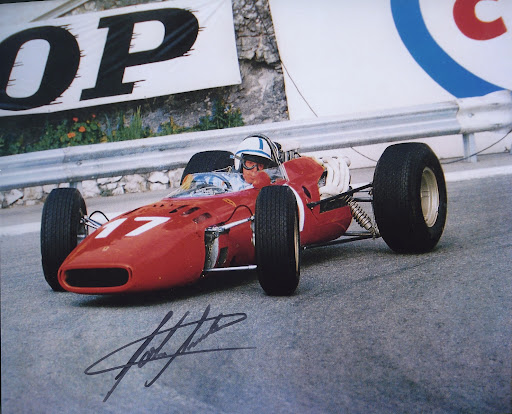
For example, in "old" f1 you could see very long arms at the rear, pointing forwards.
Image

It seems that in this type would be easier to deal with the loads, but a long arm seems it could buckle.

Is there any reason to use(or avoid) any specific type?


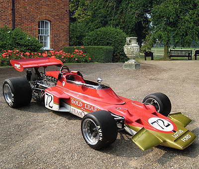
Another thing I've seen is that the rear and front inner pivot points are joined(in the front suspension).

Like this:
Image

Why would you do that? To account for chassis deformation?


Here's another picture that shows long rear control arms, almost right triangle lower front wishbone with a long rear pivot control arm. We con also see a very "small" front upper wishbone.(used also as a lever for the coilover.)
Image


Any input is welcomed!


bye bye ;)


Caito.-


PS: Some nowadays cars. Generally speaking we can see in the rear right triangles with a long front control arm. In the front, the honda for example, has right angle wishbones, seems the bmw has them too.
Image
Image
Image
Image
Image
Come back 747, we miss you!!

User avatar
mep
29
Joined: 11 Oct 2003, 15:48
Location: Germany

Re: Wishbone shape.

Post

Caito wrote:I have a question. How do you decide on wishbone shape once you've got your suspension designed.
You can't really split that process, the pick up points location define how your suspension will behave. So you rather check where you can put them and then design your suspension accordingly.
The location of the points are important for instant center location (IC), roll center (RC) location, roll, weight transfer, anti dive/squad...
However even when you have some strange locations of them you can still get your suspension done.
Caito wrote:Here's another picture that shows long rear control arms, almost right triangle lower front wishbone with a long rear pivot control arm. We con also see a very "small" front upper wishbone.(used also as a lever for the coilover.)
Image
That’s a good example. You can see the engine is mounted as structural part of the car and takes a lot of space in front of the suspension. So you would have to mount something to the side of the engine to attach the wishbone there. Better is to make the wishbone longer and mount it directly to the tube, therefore you get a better loadpath to the front of the car and reduce the load on the engine. The solution on the front has a special name (which I äähm forgot). Basically the top wishbone acts like a rocker. The problem is that it is heavier because it has to take bending loads and that the ratio of wheel to spring movement is limited. The leverage of the spring is much shorter than the one of the tire and so the spring will move little compared to the wheel.

Image
The design of the front wishbones could also be lead by mounting positions because the tube ends right in front of them but we see some variation between the cars here. Basically the front wheel gets braking and cornering forces so the wheels get pushed to the sides and backwards. The backward forces goes through the backwards pointing strut to the rear. So it’s a matter of load path again. It’s also important to know that the struts interact with each other so you can create situations where the force in one strut gets reduced because of the angle of the other or when you corner and brake at the same time.

marcush.
marcush.
159
Joined: 09 Mar 2004, 16:55

Re: Wishbone shape.

Post

first a lot of your hardpoints are fixed by position of the bulkheads or even by the regs.
A closed triangle wishbone is a sfe thing ..usually the bar along the monocoque is called anti intrusion bar for a reason and some sanctioning bodies demand for these.
So in effect the law of physics will dictate the shape. :wink: easy as that.you just don´t draw up the thing and then stuck it somewhere .In a thought out process the pieces literally fall in place as you take decisions along the way.
you would not start with the wishbone design ... :mrgreen:

User avatar
Tim.Wright
330
Joined: 13 Feb 2009, 06:29

Re: Wishbone shape.

Post

Once you have your initial set of pickup points which give you the correct camber gain, bumpsteer, steering geometry etc. Then there is some freedom to move the inboard points on the A-arms.

On a given wishbone, the two inboard points can be moved anywhere along the axis of rotation of the wishbone without changing the kinematics.

So basically, the shape of the arm has more to do with the loads (and where to feed them) than the kinematics. For example on the modern F1 pics, the a-arms of the front axle have their leading edge almost perpendicular to the centreline because thats where the tub ends. The trailing edge angle would then be solved based on some braking and lateral load cases.


Tim
Not the engineer at Force India

riff_raff
riff_raff
132
Joined: 24 Dec 2004, 10:18

Re: Wishbone shape.

Post

Caito,

The classic double wishbone suspension arms and links are basically tension/compression members. In simple kinematic terms, almost every individual joint of the suspension (think of spherical bearings) has full freedom in rotation, but is fully constrained in translation. So by definition, the suspension linkage elements can only transmit translational forces along a vector that passes through the joint center nodal points. If you picture a pair of upper/lower A-arms, tie rods, and their upright, you'll note that all loads produced at the wheel must be reacted by translational forces through the linkage nodal points. The most structurally efficient way to connect the linkage joints is by straight tension/compression members. Thus you end up with the typical A-arms and tie rods.

As for the relative angles of the A-arm legs, these are determined by loads. The A-arms must react vertical/horizontal wheel forces, as well as braking/acceleration moments at the wheel. The A-arm legs may be subject to both compression and tension forces. Spreading the legs of the A-arm apart, as well as orienting them so that they're not parallel to the wheel axis, usually results in lower compressive loads in the legs.

Of course, as Tim.Wright points out, sometimes packaging requirements override good structures practice.

Regards,
riff_raff
"Q: How do you make a small fortune in racing?
A: Start with a large one!"