How is the engine/gearbox assembly mounted to the tub?

All that has to do with the power train, gearbox, clutch, fuels and lubricants, etc. Generally the mechanical side of Formula One.
Formula None
Formula None
1
Joined: 17 Nov 2010, 05:23

Re: How is the engine/gearbox assembly mounted to the tub?

Post

More pics F1snake took of his RA 107-05:

Image

Image

User avatar
ringo
230
Joined: 29 Mar 2009, 10:57

Re: How is the engine/gearbox assembly mounted to the tub?

Post

This thread is quiet all of a sudden? :wink:
We get what we wanted to see and no posts?
That bolt looks interesting.

found this on shell motorsport's twitter:
Fact of the day: Due to heat transfer, the fuel in a Formula One car can get as hot as a cup of tea!
how hot is a cup of tea? :D
For Sure!!

Formula None
Formula None
1
Joined: 17 Nov 2010, 05:23

Re: How is the engine/gearbox assembly mounted to the tub?

Post

In the South, about 35-40F.

riff_raff
riff_raff
132
Joined: 24 Dec 2004, 10:18

Re: How is the engine/gearbox assembly mounted to the tub?

Post

ringo wrote:This thread is quiet all of a sudden? We get what we wanted to see and no posts?
Ringo,

With that deep vertical notch for the oil tank, that tub bulkhead structure will have very little transverse shear stiffness. So any strains due to thermal mismatch between the composite tub and metal engine should not produce excessive stresses. As for the tub bulkhead shear stiffness in the vertical direction (between the upper and lower engine studs on each side), that would depend upon the particulars of the composite lay-up, which we can't see.

regards,
riff_raff
"Q: How do you make a small fortune in racing?
A: Start with a large one!"

User avatar
ringo
230
Joined: 29 Mar 2009, 10:57

Re: How is the engine/gearbox assembly mounted to the tub?

Post

Image

The groove adjacent to the threaded part, what's the purpose of it?
Is there a collar on the cylinder head that slots over the groove, keeping the engine on the bolt in the event of a thread/nut failure?

I agree about the mismatch not producing much stress transversely.
Vertically, i don't think there will be a big issue. The temperature differences may be too small to create much strain. A cup of tea, may be about 80 degrees C?
The engine face, may be at water or oil temperature?

The composite layup is interesting, i know little about it. Maybe it's better to have the engine as the less stiffer part. The metal is more forgiving in that sense.
For Sure!!

marcush.
marcush.
159
Joined: 09 Mar 2004, 16:55

Re: How is the engine/gearbox assembly mounted to the tub?

Post

the colar is simply there to centre the bolt in the bolt hole ,especially when torquing the nut ,there would be the tendency to bend the long bolt leading to false torquereadings.that´s my interpretation of it.also it will on slipping on the engine prevent the thread to rub and dig too much into the bolt hole when a small misalignment is present .

It looks like they have not in any ways allowed for the mismatch over temperature and it is not obvious how they allow for the overconstraining of the interface(more than three fixed points )So this has to be somehow catered for by the engine mounting points?

The issue of the open U-profile of the tub to allow for the engine expansion ,is it really as flexy in that area with Aluminium honeycomb core and possibly ti inserts in these areas ,I´d really want to know how much flex is in those single points.

User avatar
ringo
230
Joined: 29 Mar 2009, 10:57

Re: How is the engine/gearbox assembly mounted to the tub?

Post

I guess they took metal off the bolt where they don't need it then.

About the expansion, this goes back to what i was saying. Expansion can be converted to stress by retraining it. I posted 2 examples, and i think nsmikle had another.
It's nothing conflicting. Temperature doesn't have to be a concern if the parts have enough strength left in them after the full design stress is considered.

I am not sure if there is any mechanism on the engine to allow for movement. Movement is not what we want. That would affect the chassis' rigidity.

It's easier to design the cylinder head to take the micro-strains.
For Sure!!

marcush.
marcush.
159
Joined: 09 Mar 2004, 16:55

Re: How is the engine/gearbox assembly mounted to the tub?

Post

don´t you think stressing key areas with loads they are not part of your design philosophy (ignoring loads)is somthing an engineer should avoid?

Maybe the Interface between Hub and engine is an area with low consequence for ignorance,especially in the light of how often the engine gets separated from the tub aftzer each day of running ..so if there is some mushy things happening maybe it´s not as severe as a snapped bolt..But we do not know if these bolts a re considered service parts to be replaced after each weekend...

On Nordschleife OEM endurance testing they replace wheelbolts every 5K kilometres ...for a reason not because they are bored..

We have seen a lot of cars in F1 with looose wheelnuts ,disintegated rims,lost wheels....this is everything BUT lazy mechanics work, you bet.
It is a general misunderstanding and lack of knowledge on the engineering/manufacturing side causing these big time catastrophic failures.
as it was experienced by almost all teams we can savely say the wheel retaining system is an area of high risk ..but still all teams use basically the same method of wheel retention ...this does not make it a safe or proper ways of fixing the wheel to the hub.

riff_raff
riff_raff
132
Joined: 24 Dec 2004, 10:18

Re: How is the engine/gearbox assembly mounted to the tub?

Post

ringo wrote:I guess they took metal off the bolt where they don't need it then.
ringo wrote:I am not sure if there is any mechanism on the engine to allow for movement. Movement is not what we want.
ringo,

You touched on a couple of key points. As marcush noted, that stud has a collar near the nut end threads to prevent bending in the stud, which would increase the combined stress level the stud is subject to. The reduced diameter ("waisted") section in the middle is there to make the stud more elastic in tension, and thus reduce the stress concentrations that naturally occur at the thread roots.

The shear stiffness of the tub bulkhead would logically be designed to match that of the engine structure. Having a stiffness mismatch at a rigid attachment interface would create higher stresses in one of the parts.

riff_raff
"Q: How do you make a small fortune in racing?
A: Start with a large one!"

User avatar
ringo
230
Joined: 29 Mar 2009, 10:57

Re: How is the engine/gearbox assembly mounted to the tub?

Post

I see. I guess this can only be done with FEA. These guys don't like to hear of such things on this website. :lol:

Playing the devil's advocate here, wouldn't it be easier to add that stress to design as the engine is already a stressed part? Logically it's best to have both parts matched in terms of the strain but we have had cast iron engines with aluminum cylinder heads contrary to this philosophy. It's not the ideal, but it's simpler. :wink:
don´t you think stressing key areas with loads they are not part of your design philosophy (ignoring loads)is somthing an engineer should avoid?
The loads would be part of the design philosophy, similar to how pistons are designed i would imagine. It's not the same as ignoring loads. Keep in mind i said you add it to your mechanical loads.
For example if a part has a design yield of 50,000 N/cm square but you only stress it mechanically to 30,000; considering fatigue etc. You then have an additional 20,000 to play with. Thermal mismatch could hypothetically be another 5,000 N/cm2 of compression or extension, still no where near failure.
You can actually consider that in your calculation and see if it's worth changing the design. More than likely it's not since the part doesn't yield.
So you see I'm not encouraging negligence. Just saying that I don't mind adding a few pascals here or there if it saves time and money and leaves me with a stiffer tub/engine interface.
For Sure!!

marcush.
marcush.
159
Joined: 09 Mar 2004, 16:55

Re: How is the engine/gearbox assembly mounted to the tub?

Post

lets go back to the starting point of this discussion:

the claim was: with the engine temperatures anything between ambient and say 150°C
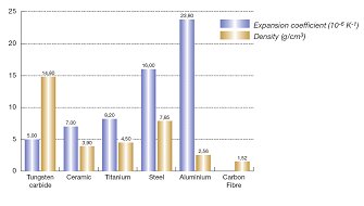
and made mainly from alumimium castings ,the tub made from carbonfibre-aluminium Honeycomb with Carbonfibre Not expanding with temperature there will be a mismatch at the Interface between engine and tub with the bolts providing the clamping force resulting in shearforces due to one structure altering their dimension whereas the other very likely not to grow over temps.

the big difference we see in this application compared to say iron /aluminium is :Iron does in fact grow as well over temp...and the thermal delta between head surface and block surface will be not big ..so the stress is only caused by the different rates of expansion and not over the differtence in temperatures of the two components.To illustrate the big difference between an aluminium /steel cobination and alumium carbonfibre combo:
Image

Now we have had the question of aluminium core in the CF sandwich ...I´d think this is only applicable for the core thickness really.the honeycomb itself is not stiff at all over in plane so it will do what ever the carbonfibre skins will do over temp(e.g.nothing basically).
and the thing with the open U structure of the tub effectively taking up the dimensional changes this maybe true for the grow in width of the engine but not
for the changes to height.So we still got the engine growing in height as it reaches running temps and taking the bolts secured in the tub with it ,causing misalignment.either when cold or when hot..take your choice and hope for the best.

User avatar
ringo
230
Joined: 29 Mar 2009, 10:57

Re: How is the engine/gearbox assembly mounted to the tub?

Post

the claim was: with the engine temperatures anything between ambient and say 150°C
and made mainly from alumimium castings ,the tub made from carbonfibre-aluminium Honeycomb with Carbonfibre Not expanding with temperature there will be a mismatch at the Interface between engine and tub with the bolts providing the clamping force resulting in shearforces due to one structure altering their dimension whereas the other very likely not to grow over temps.
yep
So we still got the engine growing in height as it reaches running temps and taking the bolts secured in the tub with it ,causing misalignment.either when cold or when hot..take your choice and hope for the best.
No it wont cause misalignment. You see the square metal surfaces, The engine clamps against those with such a high pressure that the temperature change wont cause any relative motion there. Remember as well that the bolt is basically a cantelever anchored into the tub, so it will prevent engine movement.
The engine will grow at the outer boundaries, but at the bolt holes it will be compressed. We will have stress concentrations at certain points, but this will be on a really small scale.

Even though the cfrp has a lower coefficient than cast iron. It still conforms by the same mathematical relations. So if you were to model a situation both with carbon or cast iron as the tub, the only thing that will change is the expansion coefficient of the tub. No matter how mismatched the materials the results should be similar, just that one may be more extreme.

I did a sim a while back with a cast iron block retaining an aluminum piece by 4 bolts. I exposed the aluminum to 100 degree heat. I didn't post it at the time becuase of the aggression towards FEA. :lol: I intended to use carbon, but i didn't have the physical properties at the time. There was no part failure, just some movement at boundaries. The highest stresses were near the bolt holes.

One more thing:
Though the carbon's expansion coefficient is zero it will still extend. It wont extend because of temperature, but it will see some movement from the engine pushing against it. It wont be a shear stress by it self. It will be a tensile stress, since the bolts are probably staked into the tub.
For Sure!!

marcush.
marcush.
159
Joined: 09 Mar 2004, 16:55

Re: How is the engine/gearbox assembly mounted to the tub?

Post

both materials aluminium and Carbonfibre are very stiff -and are characterissed by a high e-module .
The claim that the expanding aluminium would just carry the carbonfibre with it is contradicting the higher e-module carbonfibre is showing.
On top of that Carbonfibre is very brittle and fails at a elongation of only 0.5%...
so considering our estimated grow or elongation which was around .25% we are not tearing the thing apart in the first heatcycle but the carbonfibre should see considerable stress.Resulting in possible microruptures especially in the bonding areas where the inserts are mounted.

cf orientation could this help in that area,by putting all fibres in right angles towards the elongation direction would reduce the stiffness.but do we even want that?

User avatar
humble sabot
27
Joined: 17 Feb 2007, 10:33

Re: How is the engine/gearbox assembly mounted to the tub?

Post

it's one thing to reduce stiffness and another to reduce strength. You'd be relying entirely on the matrix in that case silly :)


@ringo: what do you mean by 'staked'? the wall thickness can't be too great in that area as the portion enclosing the fuel bladder is supposed to be deformable.
the four immutable forces:
static balance
dynamic balance
static imbalance
dynamic imbalance

User avatar
humble sabot
27
Joined: 17 Feb 2007, 10:33

Re: How is the engine/gearbox assembly mounted to the tub?

Post

I keep looking for shots of the studs. Here's one:

(the owner has disabled downloading of their photos)

http://www.flickr.com/photos/wenny_wu/2 ... 1/sizes/l/
the four immutable forces:
static balance
dynamic balance
static imbalance
dynamic imbalance