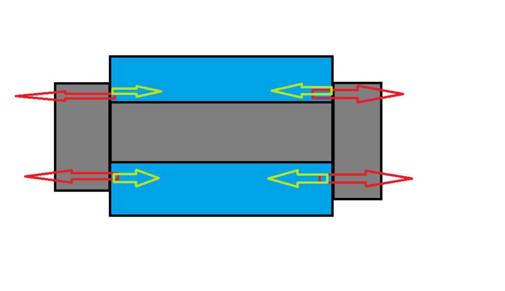
F1 pankl conrod

All that has to do with the power train, gearbox, clutch, fuels and lubricants, etc. Generally the mechanical side of Formula One.
User avatar
ringo
230
Joined: 29 Mar 2009, 10:57

Re: F1 pankl conrod

Post

F1_eng wrote:The groove in the cap to con-rod mating surface is used to alter the magnitude of the fluctuating load component in the bolt.
The ratio of the total fluctuating load taken by the bolt is dependant on the relative stiffnesses between the two components.

I am not going to say anymore as I feel that is enough information for people to do more research if they wish.
What is the groove doing exactly?

How does it alter the bolt tension, or slight bending?
And what's the relationship to the width of the groove?
For Sure!!

xpensive
xpensive
214
Joined: 22 Nov 2008, 18:06
Location: Somewhere in Scandinavia

Re: F1 pankl conrod

Post

I think smikle is correct, the mating surfaces are not completely parallell, why the groove is there to identify two separate
contact patches, one on either side of the bolt, all in order to avoid any convex curvature in said mating surfaces.
"I spent most of my money on wine and women...I wasted the rest"

F1_eng
F1_eng
4
Joined: 05 Aug 2009, 11:38

Re: F1 pankl conrod

Post

riff_raff, you could look this up in a book, I'm sure there are a lot of books out there that explain it.

I don't quite see what you are saying in your post.

You will agree that the bolt stretch must be the same as the compression in the cap. You have now got a strain in the two components due to the pre-load which is equal in magnitude. The force required to cause this strain is different for the bolt and cap since their stiffnesses are different.
The inertia load at TDC Exhaust will stretch the bolt further but this will also serve to reduce the compression between the cap and con-rod. So the inertia causes an additional bolt force but the reduced compression between the cap and rod reduces the force. The net force difference which is your fluctuating force is dependant on the relative stiffnesses of the bolt and con-rod, it is not a 1:1 relationship though.

Try and understand it first rather than assume it's not right. If you fail to understand it after an attempt, I can derive it mathematically for you if you would prefer.

Books on machine dynamics and that sort of this would most probably have something about it, look for bolted joints or something like that.

ringo, the grove is changing the stiffness of the section which is deformed during pre-load.

User avatar
PlatinumZealot
559
Joined: 12 Jun 2008, 03:45

Re: F1 pankl conrod

Post

F1 eng, the stiffness of that little section at the interface still wouldn't affect the shape of the circle much. Cutting out that notch, you would get like micro strains difference! The bolt is extremely strong so it might even be smaller. And that crush/stretch is only a tiny percentage of the whole circumference of the bearing. That doesn't do much for the actual shape of the bore.

You see, you are all focusing on the strains at that interface. Where the elephant in the room is that the diameter of that thing varies from 38mm to 37.5mm.
πŸ–οΈβœŒοΈβ˜οΈπŸ‘€πŸ‘ŒβœοΈπŸŽπŸ†πŸ™

Racing Green in 2028

F1_eng
F1_eng
4
Joined: 05 Aug 2009, 11:38

Re: F1 pankl conrod

Post

I don't know what to say n smikle, I can't understand the terminology you are using.

My post had nothing to do with the shape of the circle, whichever circle that is.
The bolt is extremely strong so it might even be smaller? micro strains?
And that crush is only a tiny percentage of the whole circumference of the bearing?
I have no idea what you are talking about, perhaps you don't either.

My post was refering to the alternating load that the bolt has to deal with, that "notch" is a way of tuning the portion of this alternating force that the bolt has to deal with.

Why do you guys think high quality racing bolts most often have a wasted shank?

If you don't know the answer, you don't need to say anything and prove to everyone else you don't know. You could just say nothing.

User avatar
PlatinumZealot
559
Joined: 12 Jun 2008, 03:45

Re: F1 pankl conrod

Post

I know what I am talking about. I don't know why you don't know.

I am talking about the big end bore of the conrod.
You are talking about the bolt interface, Which only would have very small orders of distortion, not enough to affect the shape of the bore.

We can go right down to the small details if you want. :wink:

But you are familiar with stresses in hoops right?
πŸ–οΈβœŒοΈβ˜οΈπŸ‘€πŸ‘ŒβœοΈπŸŽπŸ†πŸ™

Racing Green in 2028

User avatar
PlatinumZealot
559
Joined: 12 Jun 2008, 03:45

Re: F1 pankl conrod

Post

I think I have to draw a diagram.
πŸ–οΈβœŒοΈβ˜οΈπŸ‘€πŸ‘ŒβœοΈπŸŽπŸ†πŸ™

Racing Green in 2028

Formula None
Formula None
1
Joined: 17 Nov 2010, 05:23

Re: F1 pankl conrod

Post

Interesting analogy with a waisted shank bolt, F1 eng. You're saying the width and depth of the channel cut on the face affects the amount of deformation in the end cap, in effect dampening the peak loads? If the channel wasn't there all of the peak loads would be transferred through the bolt alone. Am I understanding you correctly?
F1_eng wrote: If you don't know the answer, you don't need to say anything and prove to everyone else you don't know. You could just say nothing.

Smirk and ringo and going to need at lot of bold text and emoticons to adequately respond to this statement.

User avatar
PlatinumZealot
559
Joined: 12 Jun 2008, 03:45

Re: F1 pankl conrod

Post

You will agree that the bolt stretch must be the same as the compression in the cap. You have now got a strain in the two components due to the pre-load which is equal in magnitude.
This is not true because the bolt is threaded. That means It can move relative to the conrod material. The conrod material is also less stif so it will start compressing before the bolt.

So it is wrong that the extensions are equal.

The he says this..
The force required to cause this strain is different for the bolt and cap since their stiffnesses are different
Which is wrong.. the force is what is equal. There is full contact between the bolt and the material and the only thing resisting the motion of the bolt once it is tightened is the conrod material itself. The net force MUST BE ZERO IN THIS CASE. Fundamentals...

Image
πŸ–οΈβœŒοΈβ˜οΈπŸ‘€πŸ‘ŒβœοΈπŸŽπŸ†πŸ™

Racing Green in 2028

User avatar
PlatinumZealot
559
Joined: 12 Jun 2008, 03:45

Re: F1 pankl conrod

Post

You know, I was more interested in how the mating interface affects the shape of the bore.

I already feel that the bolt stretch is not enough to affect the shape of the bore at high rpm and that is why I shifted focus (some pages ago) to the not so obvious slanted angle that the mating surface is cut at.


But I will switch back over to the bolt thing.
The inertia load at TDC Exhaust will stretch the bolt further but this will also serve to reduce the compression between the cap and con-rod. So the inertia causes an additional bolt force but the reduced compression between the cap and rod reduces the force.
I agree with this.
The net force difference which is your fluctuating force is dependant on the relative stiffnesses of the bolt and con-rod, it is not a 1:1 relationship though.
There is no net force difference if the two parts are still in full contact and the bolt is under tension. Even if you account for the acceleration of the whole body (conrod + bolt) there is basically zero relative motion between the two parts. The only thing I can see in my mind's eye is internal distortions such as stretches, which are still produced by equal and opposite forces no matter how you want to slice it! These are just two bodies.


MY question to you F1 eng: (This is an honest question). thinking like a designer... what is one ultimately trying to achieve by putting the notch?

I mean, I honestly wasn't even paying you guys any mind until now because to me, the elephant in the room is the mere fact that the bore is an oval and the mating surfaces are cut slanted. But I am all ears to how the notch affects the shape of the oval.
πŸ–οΈβœŒοΈβ˜οΈπŸ‘€πŸ‘ŒβœοΈπŸŽπŸ†πŸ™

Racing Green in 2028

User avatar
PlatinumZealot
559
Joined: 12 Jun 2008, 03:45

Re: F1 pankl conrod

Post

I have a few theories of why the notch is there. These two have not to do with the shape of the bore though. Maybe this is more in line with what F1eng and riff raff were arguing about. I will give my take on it now:

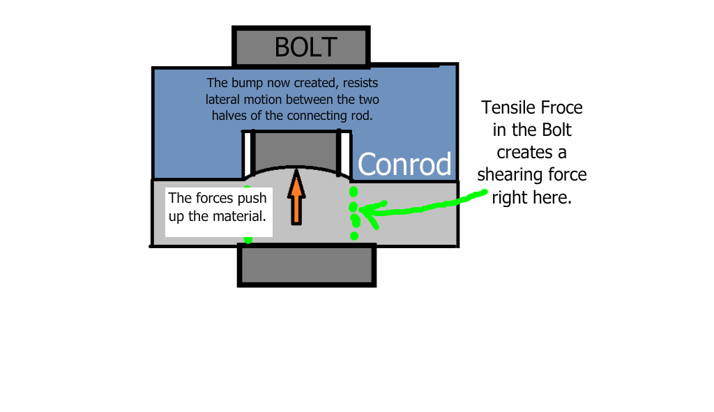
1. Clamping pressure (already mentioned). Imagine squeezing a strip of rubber with a set of pliers. The pliers are of the kind with the zig-zag teeth in the jaw. When you squeeze the rubber, the pressure from the teeth creates little hills and valleys in the rubber. This is caused by shear forces and partially by the material trying to keep a constant volume.

The little hills increases the resistance to any sliding.

So in a way, I am saying the notch is there to create a shear plane and also a place for the material to deform into. The shear force comes from the same tensile force in the bolt. I am not that good at explaining things with words so here goes...

Image

2) The notch could be an oil hole?

3) The notch could be there for some type of measuring gauge.

4) subtractive Tension/compression as the connecting rod goes up and down -
I don't think you need a notch to achieve this. But it will give it a shot in my next post.
πŸ–οΈβœŒοΈβ˜οΈπŸ‘€πŸ‘ŒβœοΈπŸŽπŸ†πŸ™

Racing Green in 2028

F1_eng
F1_eng
4
Joined: 05 Aug 2009, 11:38

Re: F1 pankl conrod

Post

I may have worded it slightly confusingly/wrongly.

If you pre-load the bolt, the bolt will be stretched F/Kb
This same force is opposed by the con-rod which will stretch F/Kc

At TDC exhaust the inertia loads can be high, particularly for an F1 engine. The bolt does not have to deal with all this inertia load as a fluctuating load. The con-rod bolts would soon fail due to fatigue if it had to deal with total fluctuating load. This is all about fatigue, for anyone that didn't appreciate that.

The amount of fluctuating load that the bolt has to deal with is dependant on the stiffness ratio between the con-rod mating joint and the bolt. It is not a straightforward ratio though. The grooves are a method of tuning the joint stiffness to either increase of decrease the bolt alternating stress.

Formula None, the wasted shank is used to reduce the stiffness of the bolt which means the fluctuating stresses are less. This significantly improves the fatigue life of the bolt.
Very often if a con-rod bolt fails, people think you need to but a bigger bolt in or a stronger material. This would mean that the bolt would have to deal with a bigger portion of the fluctuating load. The worst case scenario is the joint separates and the bolt has to deal with the total fluctuating load, which could be assumed to be 80,000N split between two bolts.
On a simple M10 bolt, this would equate to a fluctuating tensile stress of approx 510MPa. You then need to use suitable stress concentration factors and look at the endurance limit or fatigue behaviour of the material. An alternating stress of 510MPa is quite high since the mean stress for the bolt is already usually pretty close to yield. The higher the mean stress, the less the allowable alternating stress. 510MPa around a 0 mean stress would be too high for most materials.

n smikle, I very much would like to get down to the details, what did you have in mind?
Do you know how to calculate the deflection of the simplified con-rod cap region shown in the image, assume the material is steel.

http://img812.imageshack.us/i/boltedjointexample.png/

Richard
Richard
Moderator
Joined: 15 Apr 2009, 14:41
Location: UK

Re: F1 pankl conrod

Post

Can someone explain the relevance of this thread please because there's no introduction in the OP.

What is a Pankl Conrod, is it currently used, is it new, what is different about it, what are we looking at in the OP?

Out of interest, where did this thread spring from? It looks to have been cut from another discussion, the quote in the OP is a give away.

F1_eng
F1_eng
4
Joined: 05 Aug 2009, 11:38

Re: F1 pankl conrod

Post

Sorry for posting twice, I tried to edit the link.

Ofcourse the net force has to be zero in the bolted joint, but you are modifying what is happening to the forces during these huge inertia loads. Do you really think you could clamp up a bolt to say 80% of its yield then ask it to deal with another 40000N every other revolution so say 150 times a second. It wouldn't stand a chance.

http://www.kxinc.com/content/Kx%20Broch ... _Brief.pdf

That looks like a brief paper on some bolted joints and I see it has a couple of formulas there about fluctuating loads in joints, not derived though.

F1_eng
F1_eng
4
Joined: 05 Aug 2009, 11:38

Re: F1 pankl conrod

Post

The post is about the design of the Pankl con-rod shown.

n smikle, the idea about a grove allowing material to compress in to it isn't that important since the con-rod already has a locating dowell which is more than adequate to deal with any sliding force. There shouldn't be any sliding or the joint would be close to separating by which point the bolt would have already broken, the tangential force able to be resisted by the axial force is simply dependant on the friction coefficient. So if mu is 1, a 30000N axial force could resist 30000N tangential sliding force on a completely flat surface.