Exhaust Blown Floor - Forward Exhaust Exit

Here are our CFD links and discussions about aerodynamics, suspension, driver safety and tyres. Please stick to F1 on this forum.
volarchico
volarchico
0
Joined: 26 Feb 2010, 07:27

Re: Exhaust Blown Floor - Forward Exhaust Exit

Post

godlameroso wrote: I was simply stating that exhaust pulses are discreet events, and not a continuous jet with continuous pressure. If you've ever stood behind a running car and had the exhaust hit your leg, you notice that it's not flowing like wind, but rather a series of pulses. ...
So you have alternating and discreet high and low pressure waves being injected into the airstream and naturally they will follow the path of least resistance.
But I think shelly's point is you wouldn't notice those pulses if you stood behind the exhaust of an 8-cylinder engine turning at 18000 RPM. At this frequency, there are probably some complex mixing interactions going on in a highly-tuned F1 exhaust system. I could be wrong, but someone would need to analyze the time-scale associated with the exhaust gas velocity and the frequency of the pulses and the length of the exhaust pipes to see the interaction.

User avatar
godlameroso
309
Joined: 16 Jan 2010, 21:27
Location: Miami FL

Re: Exhaust Blown Floor - Forward Exhaust Exit

Post

As I wrote, I think that obscillation effect maybe is important, but I do not think it is the key factor. For example as far as merc w02 is concerned, I think that the idea behind their exahust positioning is to exploit Coanda effect like in the blown flaps of some airplane, to energise and ben inwards in the coke bottle the flow around the sidepods.


Perhaps I'm mistaken but I believe that the Coanda effect is that lift is generated when air flow is moving faster relative to the opposite side of a given surface. I can see this working only if the airflow that passes inside the chassis to cool the radiators and what have you is actually traveling faster than the air going around the outer surface of the chassis. Perhaps that's why Renault has those funky cooling exits.

I have worked on turbo cars for a good decade now, since turbos are all about using exhaust efficiently, I had to do some studying on the subject, there's still stuff I don't know, but I know for sure all exhaust is a discreet pulse all the way from the combustion chamber to the end of the exhaust tip.

If you fire a machine gun do the bullets merge as they come out of the rifle? Each bullet is a discreet event with a discreet reaction, even on full auto bullets come out one at a time. Likewise with engines, one combustion cycle produces one exhaust pulse, the collectors at the end of good headers don't converge the pulses it lines them up. Disrupting this process with badly tuned headers actually causes back pressure because the pulses are trying to fit in the same space. Regardless they exit the car as discreet pulses and not as a flow.
Saishū kōnā

gridwalker
gridwalker
7
Joined: 27 Mar 2009, 12:22
Location: Sheffield, UK

Re: Exhaust Blown Floor - Forward Exhaust Exit

Post

I've not studied exhaust technology, so I would like a quick clarification :
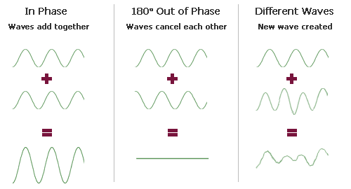
As exhaust "pulses" would effectively act as pressure waves, do they interact with each other in a classical wave interferance pattern (similar to soundwaves)?

Image

As exhaust pressure waves wouldn't generate a negative pressure at any point, the analogy can't be entirely accurate (e.g. out of phase soundwaves cancel each other out, which couldn't be the case with exhaust pulses) but I would be interested to see a diagram that describes "pulse" interactions in more detail.

Any information will be appreciated!
"Change is inevitable, except from a vending machine ..."

User avatar
ringo
230
Joined: 29 Mar 2009, 10:57

Re: Exhaust Blown Floor - Forward Exhaust Exit

Post

Raptor22 wrote:Shelly, I am on a business trip at the moment so internet connectivity is poor. Once I'm back home i'll sit down and write something up.

Basically though, Exhaust gases behave as a jet when they are expanded through a diverging nozzle i.e. Rocket engine, afterburner in gas Turbine. Typically in the throat of the nozzle gases are moving supersonic. Even here by the time the gas leaves the boundary of the nozzle the kinetic energy bleeds off rapidly. Next time you watch a rocket launch have a close look at the plume. there is a just subsonic parabolic region behind the nozzle, a defined boundary and then a large cloud of hot gas moving very slowly but expanding rapidly. In a automotive application we have a mass flow of hot gas thats not expanded via a divergent nozzle and only expands once the gas leaves the boundary of the pipe.

If We look at it simplisticly we are dealing with Q=VA.

Q Exhaust pipe must equal Q environment.

With the Renault Ringo's images give a good idea of what is going on the only assumption I think he has made incorrectly is to assume the exhaust gas is behaving as a stream. It does for perhaps around 50mm from the exit but it is exhausting into a highly turbulent flow coming off the splitter and a more streamloned flow just above the road. It is hot gas and not at ambient and there are thermodynamic effects that are difficult to model without knowing the exhaust length, flow velocity just prior to exit etc.
So yes some of the gas is going to be pulled along the side of the pod (expansion + kinetic energy is going to result in rapid dispersion), the bulk of it is going to be pulled under the car probably along the streamlines he shows but in a highly turbulent manner Since the flowclose to the ground is flwoing for directly ahead ahile flow at a higher streamline is coming off the splitter and going around the pod.
Both flows are influencing the behaviour of the exhaust gas.

If Renault has included a divergent nozzle into the exhaust pipe outlet design then I would agree with you, we could assume a Jet stream like behaviour for possibly a foot from the exhaust if the temperature and pressure is high enough. I just don't see anything resembling such a device.

You're welcome to disagree but like I said, we are not dealing with a rocket motor even though it does go like the clappers.

Other examples are Oxyacetylene torches for cutting or welding. the gas flow (exhaust there is being expanded inside a diverging nozzle and we are achieving a supersonic flow or close to it. Its this gas flwo and the proximityof the combustion that results in a jet of hot gas. These exhausts are nothing close to this. They're just exhaust pipes.
Well you see, I am going off what i am seeing in the CFD. I can't force it to behave how i think it should.
I had a theory and i loosely held onto it. Whether it was true or not was subject to CFD. It was somewhat correct and so it believed it. I don't have strong convictions for what i cannot see or calculate.
The CFD shows the exhuast as stream so i have to accept that unless i see otherwise.
The exhaust speed is 220m/s also so it is a long way from sonic speeds. The pressure wave speed is also seperate and apart from the actual gas itself.
The exhaust will only diverge if the surrounding environment is of much lower momentum.

A good way to look at it is to put the same exhaust under moving water, which obviously has much higher mass flow and momentum. The shape of the ehxuast wont be a divergent plume or even a proper stream. This is why it's not safe to conclude what is happening without actually seeing it.
So i cannot believe that the exhaust is braking 90 degrees and going down the center of the floor. It's not possible with the air speed that an F1 goes.
And generally the finite element analysis, regardless of it's accuracy, has a logical approach to it's calculations.
For Sure!!

shelly
shelly
136
Joined: 05 May 2009, 12:18

Re: Exhaust Blown Floor - Forward Exhaust Exit

Post

@godlameroso: I think that your comparison with machine gun is useful to understand everything better. If we look at the four cylinders of one bank as four synchronised machineguns, each of them spits its packet of high pressurefollowed by low pressure mass of flow. Being the primaries of the same length, these packets need the same time to travel to the junction and then queue one after the another,till the exit.

So we have a train of high pressure and low pressure packets exiting at a certain speed (which marekk has estimated with some assumptions).
Still I think it is more useful for now to concentrate on the average and forget the obscillations: in the end a turbo spins at constant velocity if throttle is held constant.

As far as the Coanda effect, I am quite sure that it just needs one source of fluid (let us say jet) and a curved surface: the effect is that the tangentially blown fluid is deviated and follows the surface; check Wikipedia maybe.

@gridwalker: I do not know much of acoustics, but I think here we are dealing with moving mass, with a net mass flow rate (subsonic) in one direction, and within this mass there are acoustic waves that propagate at speed of sound.

@ringo: I do not fully understand what is the 90 degrees turn that you can not believe. Is it from inside->outside to front->back or is it from back->front to up->down (followed suit by 90° turn to front->back, like in scarbs' sketch)?
twitter: @armchair_aero

User avatar
ringo
230
Joined: 29 Mar 2009, 10:57

Re: Exhaust Blown Floor - Forward Exhaust Exit

Post

Let's just say scarbs sketch is his interpretation. Secondly that sketch is nothing like the real thing and was made prior to any shots of the actual exhaust.

If the air bent 90 degrees the exhaust would choke. The gas would have to decelerate to almost a stand still then change direction. That deceleration would require extremely high pressure at the face of the exhaust pipe. Secondly that pressure is not present in the form of velocity pressure to begin with because the exhaust is facing away from the free stream.


it's just not natural for the air to behave as how that sketch has it. Just look to reality:
Image
Image
It will take trememndous momentum to bend the air coming out at a sharp 90 degrees.
And the engine will probably lose tremendous amounts of power if the exhausts are effectively blocked.

The CFD confirms the path of gases. Unless Dasualt Systems are making crappy products and their finite element package is garbage.

If they wanted the gas to flow directly downstream, the face of the exhuast pipe would need to be almost facing back directly. And the gases would need to push against the influx of air coming in from the under splitter.

The Renault pipes don't have enough angle to ram air down along the car. Secondly the momentum of the gases at 220m/s wont just suddenly take a sharp bend out of nowhere.
It will have a turning radius before it goes downstream. And it's very likely this turning radius is near the edges of the floor. The CFD confirms this as well.

So i don't see why it's so hard to believe all the evidence in the form of temp stickers on the wishbones and engine cover of the r31, over speculation.

why the hesitation? :wink:

edit: if Renault want the gases to go under the car, they will steepen the angle of the pipes as the season goes on.
Last edited by ringo on 18 Mar 2011, 20:15, edited 1 time in total.
For Sure!!

marekk
marekk
2
Joined: 12 Feb 2011, 00:29

Re: Exhaust Blown Floor - Forward Exhaust Exit

Post

ringo wrote:The exhaust speed is 220m/s also so it is a long way from sonic speeds. The pressure wave speed is also seperate and apart from the actual gas itself.
The exhaust will only diverge this the surrounding environment is of much lower momentum....
So i cannot believe that the exhaust is braking 90 degrees and going down the center of the floor. It's not possible with the air speed that an F1 goes.
Actually exhaust speed is much lower then 220m/s. We've discussed it already in this thread.
Anyway, main point to understand is flow follows pressure gradients
Fluid doesn't behave as bunch of bullets. Flow bending due to crossing with another flow at 90 degrees is only (small IMHO) part of whole picture.

Image

Exhaust speed (already bent a few degree backwards)decreases quickly, helped by blowing directly into high pressure area in front of outlet (we can expect really high values of dynamic pressure on this bent part of the floor, effectively chocking the flow), then is partially sucked by low pressure area under the floor. I think you will see this happen in your CFD, if you add this floor's detail to your model. And please remember - we are not looking at 100% of exhaust going under the car all way to the diffuser. Every few percent will be significant.

User avatar
ringo
230
Joined: 29 Mar 2009, 10:57

Re: Exhaust Blown Floor - Forward Exhaust Exit

Post

Where do you get your theory from? which reference?

The exhuast speed is 220m/s it's not 38m/s. Usain Bolt can run over 30m/s.


As to the flow, no human being can simply suggest where it's going. You need years of experience, and even then Willem Toet the aerodynamicist declined to make a guess.

Image

but it's a good thing you bring up this picture.
If the air is going down 90 degrees, then why is there a gurney at the edge of the floor?

We always see these gurney on down-force generating devices and especially when exhaust flow is involved.

Why put the gurney if the gases never get there?
For Sure!!

User avatar
ringo
230
Joined: 29 Mar 2009, 10:57

Re: Exhaust Blown Floor - Forward Exhaust Exit

Post

marekk wrote:
Image

Exhaust speed (already bent a few degree backwards)decreases quickly, helped by blowing directly into high pressure area in front of outlet (we can expect really high values of dynamic pressure on this bent part of the floor, effectively chocking the flow), then is partially sucked by low pressure area under the floor. I think you will see this happen in your CFD, if you add this floor's detail to your model. And please remember - we are not looking at 100% of exhaust going under the car all way to the diffuser. Every few percent will be significant.
you guys are hard headed. :)
Ok i'll rebuild a simple test model of a floor to demonstrate the theory. I will say from now that nothing much will change. If it doesn't satisfy then it simply means nothing can convince you, even if renault told you the exact same thing.
For Sure!!

marekk
marekk
2
Joined: 12 Feb 2011, 00:29

Re: Exhaust Blown Floor - Forward Exhaust Exit

Post

@ringo: if you have enough time and patience, try to model dual-speed outlet. In real R31 there are 2 partitions, with significantly different exhaust speeds due to outlets curvature.

User avatar
godlameroso
309
Joined: 16 Jan 2010, 21:27
Location: Miami FL

Re: Exhaust Blown Floor - Forward Exhaust Exit

Post

gridwalker wrote:I've not studied exhaust technology, so I would like a quick clarification :
As exhaust "pulses" would effectively act as pressure waves, do they interact with each other in a classical wave interferance pattern (similar to soundwaves)?

Image

As exhaust pressure waves wouldn't generate a negative pressure at any point, the analogy can't be entirely accurate (e.g. out of phase soundwaves cancel each other out, which couldn't be the case with exhaust pulses) but I would be interested to see a diagram that describes "pulse" interactions in more detail.

Any information will be appreciated!
Think of it more as a heart beat type "pulse" except you're using air and not blood, when you read an EKG it looks more like this ---/\---, exhaust pulse is similar. Exhaust pulses are pretty hard to cancel out, most of the muffling from mufflers comes from an expanded chamber where exhaust gases slow down, which is bad for performance. By the same token you can split the exhaust on turbo cars to make them way quieter. The latest lancer Evo has a very low restriction muffler, but since the exhaust is split into two, it spreads out the pulses plus slows them down which helps muffle the sound.
Saishū kōnā

marekk
marekk
2
Joined: 12 Feb 2011, 00:29

Re: Exhaust Blown Floor - Forward Exhaust Exit

Post

ringo wrote:The exhuast speed is 220m/s it's not 38m/s. Usain Bolt can run over 30m/s.
don't think so. hardly 11m/s.
If the air is going down 90 degrees, then why is there a gurney at the edge of the floor?

We always see these gurney on down-force generating devices and especially when exhaust flow is involved.

Why put the gurney if the gases never get there.
marekk wrote:And please remember - we are not looking at 100% of exhaust going under the car all way to the diffuser. Every few percent will be significant.
Who said the gases never get there ?

shelly
shelly
136
Joined: 05 May 2009, 12:18

Re: Exhaust Blown Floor - Forward Exhaust Exit

Post

@ringo: industrial chimeny example is not relevant, because it is bouyancy driven.
Also I would suggest you to discuss more gently and not to rely too much on fluent for catia: it will give you just a very rough estimate of what is going on.

@marekk: we had discussed before and found that exhaust speed is around 100m/s, if you remember. We have still to work on this, I think

As far as the gurney is concerned, it is there on every f1 2011 car because it works also for the not-diffuser aided flow.

I think that we have to proceed step by step and find agreement on:
- what exhausts are (jet-not jet)
-what speed could they have
-what happens to them when they are oriented as usually strem wise
-what happens to them when they are mounted like r31, or rb7, or w02

I see that there are a few constant followers of this thread(ringo, marekk, godlameroso, volarchico, raptor22) and I think that finding agreement step by step is the best way to proceed.
What do you think?
twitter: @armchair_aero

marekk
marekk
2
Joined: 12 Feb 2011, 00:29

Re: Exhaust Blown Floor - Forward Exhaust Exit

Post

shelly wrote:@marekk: we had discussed before and found that exhaust speed is around 100m/s, if you remember. We have still to work on this, I think

As far as the gurney is concerned, it is there on every f1 2011 car because it works also for the not-diffuser aided flow.

I think that we have to proceed step by step and find agreement on:
- what exhausts are (jet-not jet)
-what speed could they have
-what happens to them when they are oriented as usually strem wise
-what happens to them when they are mounted like r31, or rb7, or w02
What do you think?
My view on topics:

- average exhaust speed from F1 engine less then 100m/s.
Just common sense: my car's 2,4 ltr 4-stroke engine (one pipe, 5 cm diameter) is not going to have exhaust speed of +300 km/h at 4,5 krpm - and according to ringo's calculations it should.

- flow in exhaust pipe is very complex, and much more so if you add +180 bend at the end. But as a rule of thumb, flow on the outside of the curvature will be quicker (actualy we can have some backflow near the inside wall). Separator on picture below is there for a reason - makes 2 partitions with different flow speeds. Quite smart, but i'm not sure if this realy comply with rules (2 outlets per car, i see 4).

Image

- very complex (and as we can see still developed) shape of floor's leading edge creates high pressure area (both from external stream of air and exhaust blowing at it) and directs exhaust from slower partition to low pressure area under sidepods.

Exhaust from quicker partition forms sort of jet (understood as part of flow with good defined boundary to external air) few lenghts of pipe's diameter long, is slowed down fighting against high pressure area and leaves the floor just under gurney and further attaches to the flow around sidepod's undercut.
This decreases boundary layer's thickness, prevents to some extent flow around sidepod from detaching (due to pressure decrease from hot gases as they cool along the way), so you can use steeper sidepods angle at the back (in plan view).

- it's quite complex system, you need realy powerful CFD, wind tunel and lot of on-track time to tune it.

Lot of cons: loss of max engine power, loss of fuel efficency (you have to use retarded ignition to keep car's balance when off throttle), heavy (long pipe, insulation), increased frontal area of sidepods due to packaging/cooling needs.
This concept must be quite powerful, if they'll decided to go this way trying to cover 1s gap to RBR, Ferrari and Macca's.

Biggest part of exhaust's energy is stored in higher then ambient temperature and is given back as gases cool down - the more time you have to do something with this energy, the more possible gain. From this point of view, R31 > W02 > RB7/F150. But of course you have to look at whole package.

User avatar
ringo
230
Joined: 29 Mar 2009, 10:57

Re: Exhaust Blown Floor - Forward Exhaust Exit

Post

shelly wrote:@ringo: industrial chimeny example is not relevant, because it is bouyancy driven.
Also I would suggest you to discuss more gently and not to rely too much on fluent for catia: it will give you just a very rough estimate of what is going on.
So you are suggesting that we mere mortals are more credible?
A rough estimate from these FE software is the best we can do.
As far as the gurney is concerned, it is there on every f1 2011 car because it works also for the not-diffuser aided flow.
that's a very broad statement , and how can the gurney, which is slotted if we look closely, work if it's parallel to the flow?
The flow wont impact it.

I think that we have to proceed step by step and find agreement on:
- what exhausts are (jet-not jet)
-what speed could they have
-what happens to them when they are oriented as usually strem wise
-what happens to them when they are mounted like r31, or rb7, or w02
- what exhausts are (jet-not jet)

they are simply outlets for mass to pass through. Their behavior is subject to the external conditions and the shape of the outlet. What happens right before the exit is calculable, but outside of that it has to be observed, no one can predict these things precisely.
whether it's a jet is not relevant, and the name doesn't help describe the behavior.


-what speed could they have


2.4 lt engine
exhaust stroke every 2 cycles which is 9,000 cylces per minute gives 150 exhaust events per second.
for half the engine it's 1.2lt of air per side.

so it's 150 events every second x 1.2 lt = 180 l/s being pumped out

180lt = .18 m3 times the density of air at ambient which is 1.2kg/m3 = 0.216kg/s using density at ambient.

mass flow does not change, so we use ambient to find unchanging mass of air and we stick with this mass from now on.

at 850 degrees, density of air is now 0.31kg/m3 , mass is still the same.


for a pipe diameter of 2.5 inch, it's area = 0.00316 m2

using our known and constant mass of air passing this crossection of exhuast pipe everysecond,

it's velocity = mass flow/[density (at 850C) x area] = 0.216 / 0.31 x 0.00316 = 220m/s

this is maximum speed, but it's a linear relationship. so at 14,000rpm the speed would be 171m/s.

-what happens to them when they are oriented as usually strem wise
-what happens to them when they are mounted like r31, or rb7, or w02

the last 2 questions is anyone's guess.

I would add to this list, what purpose does a gurney serve, and in which positions is it intended to work. That should shed light on what is taking place.
For Sure!!