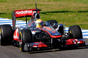
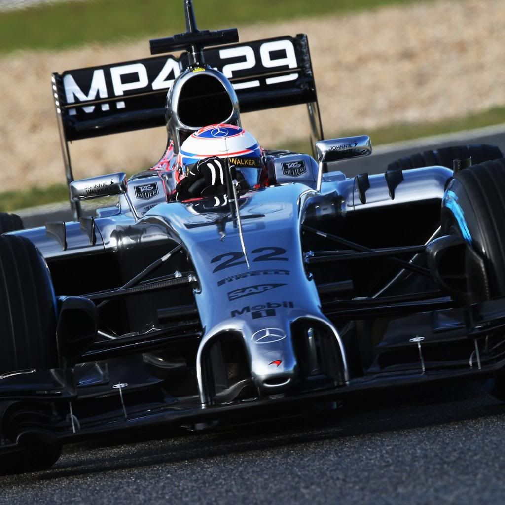
McLaren MP4-26 Mercedes

A place to discuss the characteristics of the cars in Formula One, both current as well as historical. Laptimes, driver worshipping and team chatter do not belong here.
alelanza
alelanza
7
Joined: 16 Jun 2008, 05:05
Location: San José, Costa Rica

Re: McLaren MP4-26 Mercedes

Post

LotusF1 wrote:
alelanza wrote:
LotusF1 wrote:
you dont extend them cause there is a disconnection...anyways..we might be all wrong hahahaha...
What disconnection is that?
they are connected to the rear wing but disconnected to the diffuser...so they are not an extension of the diffuser fences, rather a low pressure zone to increase velocity and hence extration to the diffuser..
Really?? ... and i thought there was some invisible material connecting them... just like the two elements of the rear wing are magically connected to each other....
Alejandro L.

User avatar
raymondu999
54
Joined: 04 Feb 2010, 07:31

Re: McLaren MP4-26 Mercedes

Post

There is. It's basically the emperor's new rear wing endplates :mrgreen:
失败者找理由,成功者找方法

marekk
marekk
2
Joined: 12 Feb 2011, 00:29

Re: McLaren MP4-26 Mercedes

Post

bot6 wrote:I think it also helps to isolate the diffuser itself from the turbulence caused by the spinning rear wheels. It might not be the main effect, but it certainly would help diffuser efficiency.

Also, if you look at the angle of those fins compared to the fences in the diffuser, the "cheese grater" seems to be accompanying the flow out of the diffuser more than really turning it. Considering the chord and span of those little foils, I doubt they have enough area to effectively change the direction of the flow, which is why I think they are mostly there to guide and stabilise rather than bend the airflow.
They are to high to only serve as diff extension.
Small surface area, but multiple elements and quite big angle of attack - i think one can expect significant change of flow direction.

4 purposes IMO:

- filling the void behind rear tyre helps with drag
- low pressure/high speed area on the inside directs diff vortexes outside and connects to one of 2 strong vortexes behind the tyre (aerodynamic diff sidewall extension, sort of)
- strong vortex created at lower tips seals diff to some extend in vertical plane and is low pressure, which helps further with diff efficiency.
- pressing both vortexes behind rear tyre to the outside.

Draggy, but must be worth it.

bot6
bot6
0
Joined: 02 Mar 2011, 19:30

Re: McLaren MP4-26 Mercedes

Post

With the lower tips of the foils connected together, I don't think there's a major trailing vortex caused by the system. But apart from that third point, I think it's a pretty good summary of the way this works.

marekk
marekk
2
Joined: 12 Feb 2011, 00:29

Re: McLaren MP4-26 Mercedes

Post

bot6 wrote:With the lower tips of the foils connected together, I don't think there's a major trailing vortex caused by the system. But apart from that third point, I think it's a pretty good summary of the way this works.
Not very big deal with those vortexes of course, but circulation around the foils have to go out somewhere, and endplate just make more of foils area effective, increasing vortex strengh IMO.

bot6
bot6
0
Joined: 02 Mar 2011, 19:30

Re: McLaren MP4-26 Mercedes

Post

Actually it does exactly the opposite: It makes the foil more effective by decreasing the vortex strength.

Basically, the foil bends the flow by being in the way of it right? So its presence will create a higher pressure on one side and a lower pressure on the other. The air will therefore try to go around the foil from the high to the low pressure zone. That is what creates the vortex, that circular movement of air from high pressure zone to low pressure zone.

But by doing that, the air moving to the low pressure zone diminishes the pressure difference between the two sides, hence diminishing the efficiency of the foil.

If you add the end plate, the movement of air from high to low pressure around the tip of the foil is made more difficult. Therefore, the vortex is weakened.

And at the same time, if that movement is slowed down, less air comes from the high pressure to "fill" the low pressure on the foil, hence more pressure difference between the two zones, hence better efficiency.


It's all about remembering that the vortex is created by the pressure difference on the foil. Not the other way around. You actually have a better chance of making an efficient foil if you diminish the vortex.

User avatar
PlatinumZealot
559
Joined: 12 Jun 2008, 03:45

Re: McLaren MP4-26 Mercedes

Post

It's just pushing the air out away from the diffuser exit that's all.
🖐️✌️☝️👀👌✍️🐎🏆🙏

Racing Green in 2028

shelly
shelly
136
Joined: 05 May 2009, 12:18

Re: McLaren MP4-26 Mercedes

Post

I think the main reason of these cheese grates is avoiding spoiling of the central channel flow by the lateral channel flow.
There is a significant difference in ressure betwen the lateral channel and the channel; pressure is higher in the lateral channel: it is this difference that creates the votex around the diffuser fence.
With the cheese grate you get a longer fence that postpones mixing of the flow form the two channels and empasizes thte downforce producing vortex of the diffuser fence.
twitter: @armchair_aero

marekk
marekk
2
Joined: 12 Feb 2011, 00:29

Re: McLaren MP4-26 Mercedes

Post

bot6 wrote:Actually it does exactly the opposite: It makes the foil more effective by decreasing the vortex strength.

Basically, the foil bends the flow by being in the way of it right? So its presence will create a higher pressure on one side and a lower pressure on the other. The air will therefore try to go around the foil from the high to the low pressure zone. That is what creates the vortex, that circular movement of air from high pressure zone to low pressure zone.

But by doing that, the air moving to the low pressure zone diminishes the pressure difference between the two sides, hence diminishing the efficiency of the foil.

If you add the end plate, the movement of air from high to low pressure around the tip of the foil is made more difficult. Therefore, the vortex is weakened.

And at the same time, if that movement is slowed down, less air comes from the high pressure to "fill" the low pressure on the foil, hence more pressure difference between the two zones, hence better efficiency.


It's all about remembering that the vortex is created by the pressure difference on the foil. Not the other way around. You actually have a better chance of making an efficient foil if you diminish the vortex.
You are right - without endplates airfoils lose efficiency near wing's tip due to lateral flows from high to low pressure regions, but this doesn't weaken sheded vortexes, just shifts vortex shedding regions from wing tip do endplate. There is significant change in vortex shape (2 of them at first) and shedding frequency, but total energy of shedded vortexes increases with increased wings downforce/lift.

Drag reduction as observed in low loaded wings (airliners at cruise speed) equipped with winglets is due to bigger aspect ratio (more aspect ratio = more efficiency).

reference: http://espace.library.uq.edu.au/eserv/U ... _16_07.pdf

marekk
marekk
2
Joined: 12 Feb 2011, 00:29

Re: McLaren MP4-26 Mercedes

Post

shelly wrote:I think the main reason of these cheese grates is avoiding spoiling of the central channel flow by the lateral channel flow.
There is a significant difference in ressure betwen the lateral channel and the channel; pressure is higher in the lateral channel: it is this difference that creates the votex around the diffuser fence.
With the cheese grate you get a longer fence that postpones mixing of the flow form the two channels and empasizes thte downforce producing vortex of the diffuser fence.
This is possible IMO, strong central vortex should bend less then weaker outer vortex, so effectively they get separated.

bot6
bot6
0
Joined: 02 Mar 2011, 19:30

Re: McLaren MP4-26 Mercedes

Post

Marekk, I think we'll have to agree to disagree on this, unless you're talking about vortexes within the spinning wire model but then it's a completely different ballgame unrelated to the actual physical phenomenon.

User avatar
Shaddock
0
Joined: 07 Nov 2006, 14:39
Location: UK

Re: McLaren MP4-26 Mercedes

Post

Interesting article about McLarens DRS

http://www.jamesallenonf1.com/2011/04/w ... -the-race/

What I don't understand is if the slot gap has a fixed maximum distance, why the flap doesn't articulate (more than one pivot point) in a way so that they can achieve an almost flat upper flap when activated.

Then it doesn't matter about the depth of the flap, as the leading edge rises the trailing edge falls keeping the flap with the maximum slot gap rule.

This is one way of visualising it :D

Image
Current DRS opening type.

Image

Deeper flap, but with a reduced angle of attack as the trailing edge sinks.

Has anyone ever posted images of double glazing on this forum before - (suitably embarrassed)) :oops:

i70q7m7ghw
i70q7m7ghw
49
Joined: 12 Mar 2006, 00:27
Location: ...

Re: McLaren MP4-26 Mercedes

Post

Interesting... is the maximum movement only measured relative to the lower element? What you are suggesting would also create a gap at the top of the wing, would this not factor in to the 50mm?

volarchico
volarchico
0
Joined: 26 Feb 2010, 07:27

Re: McLaren MP4-26 Mercedes

Post

IIRC, the regs state the DRS flap must be hinged at the rear edge in order to allow a "failsafe" closed position from aero forces if the actuator breaks.

User avatar
Shaddock
0
Joined: 07 Nov 2006, 14:39
Location: UK

Re: McLaren MP4-26 Mercedes

Post

volarchico wrote:IIRC, the regs state the DRS flap must be hinged at the rear edge in order to allow a "failsafe" closed position from aero forces if the actuator breaks.
Just looked up the rules:

The distance between adjacent sections at any longitudinal plane must lie between 10mm and 15mm at their closest position, except, in accordance with Article 3.18 (DRS activated), when this distance must lie between 10mm and 50mm

"When viewed from the side of the car at any longitudinal vertical cross section, the physical point of rotation of the rearmost and uppermost closed section must be fixed and located no more than 20mm below the upper extremity and no more than 20mm forward of the rear extremity of the area described in Article 3.10.2 at all times" It looks like it just needs the physical attatchment 20mm below the top, not really very specific, maybe a loop hole waiting to be expoited.

"The design is such that failure of the system will result in the uppermost closed section returning to the normal high incidence position" As long as the flap isn't completley horizontal, then this wouldn't be an issue.