Ringo F1 design

Post here information about your own engineering projects, including but not limited to building your own car or designing a virtual car through CAD.
gridwalker
gridwalker
7
Joined: 27 Mar 2009, 12:22
Location: Sheffield, UK

Re: Ringo F1 design

Post

A quick question about the DRS : wouldn't this fail to make the most of the 5cm slot-gap across the full width of the rear wing? If the central section opens up to 5cm, the edges of the flap will not have a gap of 5cm due to being closer to the hinge-point. If the flap edges open up to 5cm, the central section will be illegal due to having a gap greater than 5cm.

Because you cannot make the maximum use of the slot-gap across the full breadth of the wing, it seems to me that this design will not be able to shed as much drag as a conventional design with a straight edged flap. What benefits do you think your design would have over a more conventional layout?
"Change is inevitable, except from a vending machine ..."

marcush.
marcush.
159
Joined: 09 Mar 2004, 16:55

Re: Ringo F1 design

Post

gridwalker wrote:A quick question about the DRS : wouldn't this fail to make the most of the 5cm slot-gap across the full width of the rear wing? If the central section opens up to 5cm, the edges of the flap will not have a gap of 5cm due to being closer to the hinge-point. If the flap edges open up to 5cm, the central section will be illegal due to having a gap greater than 5cm.

Because you cannot make the maximum use of the slot-gap across the full breadth of the wing, it seems to me that this design will not be able to shed as much drag as a conventional design with a straight edged flap. What benefits do you think your design would have over a more conventional layout?
maybe the geometrical loss is more severe than the actual flow ? with throttle blades you quite often get only tiny effects when not openeing the full 100% ..

User avatar
PlatinumZealot
559
Joined: 12 Jun 2008, 03:45

Re: Ringo F1 design

Post

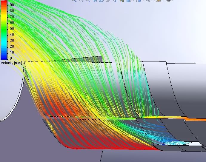
ringo wrote:Image

This is a different wing from the f duct discussion days. But it demonstrates the air speeds across the wing well.

I think the flow is close to zero because of the slot, and reciculation in that F-duct test, but you have to bring a CFD of a regular wing to really see how much slower the flow at the middle is than at the endplates.
🖐️✌️☝️👀👌✍️🐎🏆🙏

Racing Green in 2028

User avatar
ringo
230
Joined: 29 Mar 2009, 10:57

Re: Ringo F1 design

Post

gridwalker wrote:A quick question about the DRS : wouldn't this fail to make the most of the 5cm slot-gap across the full width of the rear wing? If the central section opens up to 5cm, the edges of the flap will not have a gap of 5cm due to being closer to the hinge-point. If the flap edges open up to 5cm, the central section will be illegal due to having a gap greater than 5cm.

Because you cannot make the maximum use of the slot-gap across the full breadth of the wing, it seems to me that this design will not be able to shed as much drag as a conventional design with a straight edged flap. What benefits do you think your design would have over a more conventional layout?
I was thinking about that. But i will have to see what results the CFD gives.

Whatever the case, it is somewhere between the mercedes and the Mclaren wing.

My pivot point is at the maximum allowed distance from the trailing edge.
Secondly keep in mind how much wing is cut away behind the big flap part.

It's unpredictable what will happen, i will try and do an isolated test and get some rough results in quickly comparing 3 wings. Big flap, small flap, and hybrid.
For Sure!!

Guille
Guille
0
Joined: 30 Jun 2011, 21:33

Re: Ringo F1 design

Post

I'm loving the design. I've starte to use solidworks a week ago after seeing some F1 designs in this websites and I'd really want to get going with this. I've seen a few tutorials with the basics, but there are no more, and I don't see how I can relate the tutorials to a design of an F1. If you wouldn't mind giving me some tips could you contact me at guillermo-base7@hotmail.com thanks in advance.

User avatar
ringo
230
Joined: 29 Mar 2009, 10:57

Re: Ringo F1 design

Post

Image

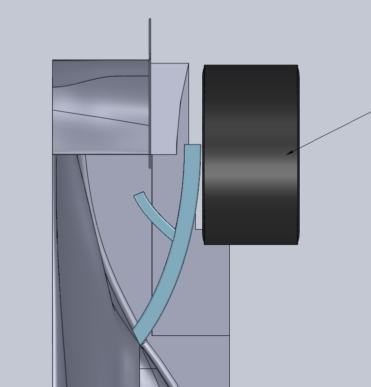
New exhuast. Seems to be like the mythical octopus....

It has 4 exits, how is this legal?


Look closely.

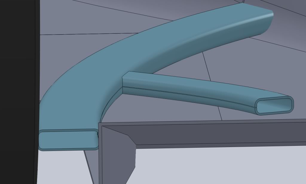
Image


This is a single exit per bank.
This is the basic concept, i'll have to fine tune the cross sectional areas.

It's the hybrid exhuast. Blows like the redbull and merceds at the same time.
Later i'll have to investigate if it's worth blowing on top of the floor, but for now this is the innovation.

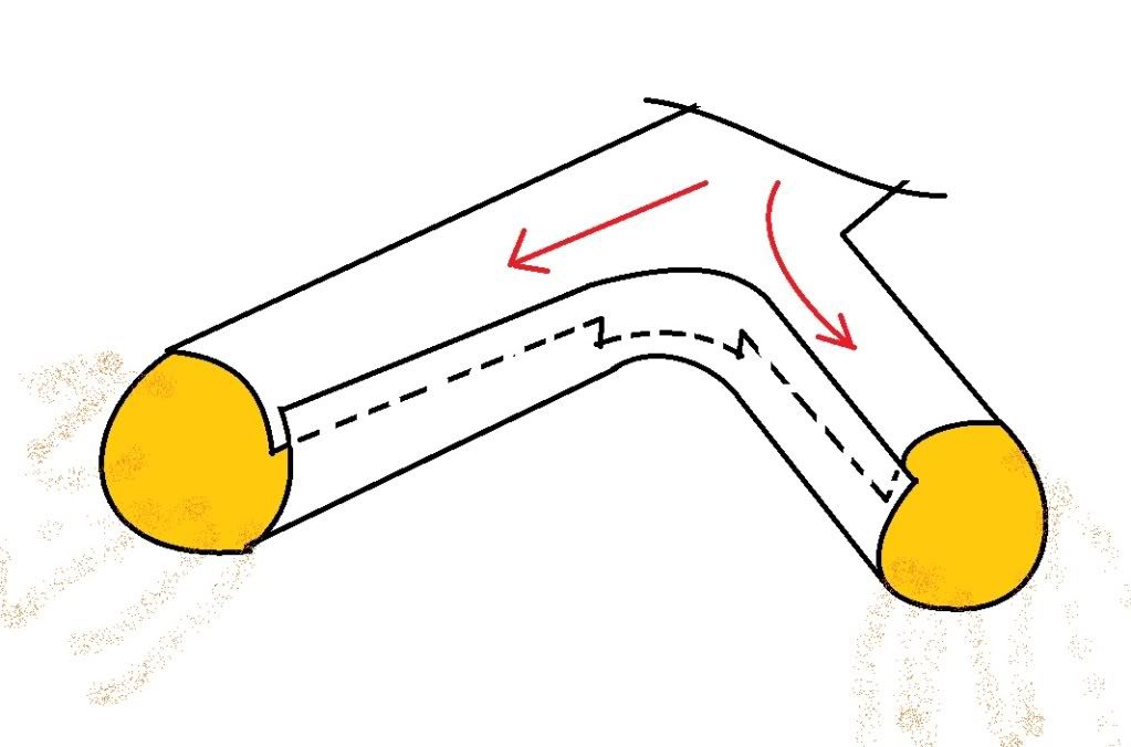
This is the concept:

Image

There is really one opening, if we consider the pipe is like a swiss roll.

The gases wont really leak out of it much because the roll gap is close, probably 5 thousandths of an inch or so. not only that but it is formed in a way that the inside act as a shield to the gap, deflecting the gas towards to main holes which are a path of lower restriction.
For Sure!!

User avatar
ringo
230
Joined: 29 Mar 2009, 10:57

Re: Ringo F1 design

Post

3.8.4 Any vertical cross section of bodywork normal to the car centre line situated in the volumes defined below must form one tangent continuous curve on its external surface. This tangent continuous curve may not contain any radius less than 75mm :
a) the volume between 50mm forward of the rear wheel centre line and 300mm rearward of the rear
face of the cockpit entry template, which is more than 25mm from the car centre line and more than 100mm above the reference plane ;
b) the volume between 300mm rearward of the rear face of the cockpit entry template and the rear
face of the cockpit entry template, which is more than 125mm from the car centre line and more than 100mm above the reference plane ;
etc..

This leave me with 100mm to do anything. If the bottom of the floor, above the plank is 50mm tall, then you have 100m minus 50 minus a floors thickness, (maybe 3mm or so) to have a non continuous curve on the surface of your body work.
This is excluding the apertures.
3.8.5 Once the relevant bodywork surfaces are defined in accordance with Article 3.8.4, apertures, any of which
may adjoin or overlap each other, may be added for the following purposes only :
- single apertures either side of the car centre line for the purpose of exhaust exits. These apertures
may have a combined area of no more than 50,000mm2 when projected onto the surface itself. No
point on an aperture may be more than 350mm from any other point on the aperture.
This is not an issue as the single appeture is on the side pod. Where the pipes meet the body. And the aperture is also bellow the 50mm mark where the side pod volumes are defined.
5.6 Exhaust systems :
Engine exhaust systems may incorporate no more than two exits.
ok.

But what i realize here is that my exhuast pipe area is unlimited. Only the part that lies within those volumes are limited to 50,000mm2 or a 5cm x 10cm rectangle.
For Sure!!

Formula None
Formula None
1
Joined: 17 Nov 2010, 05:23

Re: Ringo F1 design

Post

That's a great interpretation of the exhaust area rule. Did you come up with it or was this one of the ideas floating around about what the octopus was? I think many of us assumed the octopus was "bodywork" which diverted exhaust from two legal exits.

I wonder if subtracting exhaust flow from the diffuser outer edges for use with the upper surface of the diffuser will be beneficial. Interesting nonetheless. Maybe the inboard fork of the exhaust could blow into the start hole or along the edge of the floor/bodywork fillet to help keep flow attached...

Giblet
Giblet
5
Joined: 19 Mar 2007, 01:47
Location: Canada

Re: Ringo F1 design

Post

The only problem I can see is this:

For that slot remain open, there will need to be spacers to keep it from closing when it gets hot. The design as I see it now might close at least in some points due to expansion, making it no longer one opening.

Spacers in the gap would also mean multiple openings.

I think its a really cool idea, but as Devil's Advocate (The FIA) there are reasons it might not fly as it stands now.
Before I do anything I ask myself “Would an idiot do that?” And if the answer is yes, I do not do that thing. - Dwight Schrute

Formula None
Formula None
1
Joined: 17 Nov 2010, 05:23

Re: Ringo F1 design

Post

You could add a double wall, or some outside ribs or brackets to help constrain the expansion & contraction. Internal structures might not be necessary.

Giblet
Giblet
5
Joined: 19 Mar 2007, 01:47
Location: Canada

Re: Ringo F1 design

Post

I'm sure there is a way around it, but as it stands now I don't think it will pass scrutineering.
Before I do anything I ask myself “Would an idiot do that?” And if the answer is yes, I do not do that thing. - Dwight Schrute

wesley123
wesley123
204
Joined: 23 Feb 2008, 17:55

Re: Ringo F1 design

Post

A great idea, although illegal next year, but there are similair fun workarounds for such things.
"Bite my shiny metal ass" - Bender

User avatar
ringo
230
Joined: 29 Mar 2009, 10:57

Re: Ringo F1 design

Post

Giblet wrote:The only problem I can see is this:

For that slot remain open, there will need to be spacers to keep it from closing when it gets hot. The design as I see it now might close at least in some points due to expansion, making it no longer one opening.

Spacers in the gap would also mean multiple openings.

I think its a really cool idea, but as Devil's Advocate (The FIA) there are reasons it might not fly as it stands now.
It's one material so it will expand uniformly.

And if it does close for some reason, no one will be there to test it when it does.

But i think it is not likely for it to close on it self, being one material and all.

If the FIA wont allow it, then they simply have to rewrite the regulations.
For Sure!!

User avatar
ringo
230
Joined: 29 Mar 2009, 10:57

Re: Ringo F1 design

Post

Formula None wrote:That's a great interpretation of the exhaust area rule. Did you come up with it or was this one of the ideas floating around about what the octopus was? I think many of us assumed the octopus was "bodywork" which diverted exhaust from two legal exits.
Completely original idea.

The octopus is not really related to this, as i think Mclaren use a different loop hole. The body work as you say.

This is more related to the Merceds vents or the Ferrari vents of last year, only applied to the pipes.
In fact this loop hole appears to break the rules, but it really doesn't as there is no restrictions on the shape of the apperture.

The dificulty with this design is to control the area of that gap. If the lenght of the gap is 20 cm, you have to make sure the thickness is pretty small, like a mm or half a mm, so it doesn't take away from the main holes' areas.
For Sure!!

User avatar
ringo
230
Joined: 29 Mar 2009, 10:57

Re: Ringo F1 design

Post

Formula None wrote:You could add a double wall, or some outside ribs or brackets to help constrain the expansion & contraction. Internal structures might not be necessary.
I can't really see it touching. Though you never know and neither will the FIA.

The amount of leakage will be interesting.
Though that leakage will be small and wont affect the running of the engine in anyway.

I'll refine the design a little and there's some more innovations coming up! :)
For Sure!!