Ringo F1 design

Post here information about your own engineering projects, including but not limited to building your own car or designing a virtual car through CAD.
User avatar
ringo
230
Joined: 29 Mar 2009, 10:57

Re: Ringo F1 design

Post

Does the regulations say that the radiators have to be metal?

pitch derived Carbon fiber has a themal conductivity of 800 W/m.K
Aluminum is 250 W/m.K

Carbon makes sense as a radiator, but then it's all limited by the conductivity of air and the water which is doing the heat exchange.

I actually have an idea for a radiator for this design. Maybe i get some time to draft it. The ehxaust isn't finished either, as it's not tuned to get a proper balance of flow in both outlets.
For Sure!!

marcush.
marcush.
159
Joined: 09 Mar 2004, 16:55

Re: Ringo F1 design

Post

ringo wrote:Does the regulations say that the radiators have to be metal?

pitch derived Carbon fiber has a themal conductivity of 800 W/m.K
Aluminum is 250 W/m.K

Carbon makes sense as a radiator, but then it's all limited by the conductivity of air and the water which is doing the heat exchange.

I actually have an idea for a radiator for this design. Maybe i get some time to draft it. The ehxaust isn't finished either, as it's not tuned to get a proper balance of flow in both outlets.
But thats only the fiber -you need a matrix (resin) to form shapes from this or alternatively you would compress the fibres to monolithic structures.I could imagine you could fill the matrix with graphit to an extend but still I´m not sure if that would promote enough heat transfer to air or water.

With a resin content of lets say 40% and the claimed heat conductivity only in longitudinal direction available ..would it be possible to come up with something significantly better than 250 W/m.k ? or would it be an alternative to look into copper which is over 400 ..and is only not used anymore because of the soldering inhibiting the heat transfer and reducing the efficiency bewlow Alumniumrads?

User avatar
PlatinumZealot
559
Joined: 12 Jun 2008, 03:45

Re: Ringo F1 design

Post

I found an article.. It is 160 W/mK in the fibre direction with 60% fibre and 40% matrix and alumina particles. They say nothing of the perpendicular direction though...

http://www.rs.noda.tus.ac.jp/~ogihara/g ... ookita.pdf

Interesting, because if carbon fibre radiators were to be used you would have to definitely find away to get the fibres perpendicular to the surface of the radiator for it to be most effective. Anybody knows such a technique?


BTw aluminum 6000 series alloys have a thermal conductivity in the range of 147 - 226 W/m-K

http://www.matweb.com/search/datasheet. ... d9c247cebf

So is it worth it? Maybe, because the conductivity of the aluminum might not be limiting the heat transfer? One has to find the heat transfer coefficient of the turbulent water inside the radiator too.
🖐️✌️☝️👀👌✍️🐎🏆🙏

Racing Green in 2028

marcush.
marcush.
159
Joined: 09 Mar 2004, 16:55

Re: Ringo F1 design

Post

http://www.heatpumpcentre.org/en/projec ... r%20hx.pdf

some research about cf fins for heat exchangers from 2006 .clearly the matrix and fibre orientation especially in the areas were discrete components are mated impose the true challenge.

But then you could mold the tubes with integrated fins elimninasting that problem with ease and reduceing the mating surfaces to attachment of the watertanks...I feel this could be a cool development...

Is formula 1 cutting edge technology ?

marekk
marekk
2
Joined: 12 Feb 2011, 00:29

Re: Ringo F1 design

Post

marcush. wrote:http://www.heatpumpcentre.org/en/projec ... r%20hx.pdf

some research about cf fins for heat exchangers from 2006 .clearly the matrix and fibre orientation especially in the areas were discrete components are mated impose the true challenge.

But then you could mold the tubes with integrated fins elimninasting that problem with ease and reduceing the mating surfaces to attachment of the watertanks...I feel this could be a cool development...

Is formula 1 cutting edge technology ?
They claim they are, so why not think about adding carbon nanotubes (3000-6000 W/mK) to the matrix ?
If there are any left, one can add some directly to cooling water (ionanofluid) and get 20-30% improvement in heat exchange rate.

User avatar
PlatinumZealot
559
Joined: 12 Jun 2008, 03:45

Re: Ringo F1 design

Post

Why don't you just add liquid sodium Potassium alloy then? It's lighter than water 8) lol
🖐️✌️☝️👀👌✍️🐎🏆🙏

Racing Green in 2028

Edis
Edis
59
Joined: 31 Jan 2010, 16:58

Re: Ringo F1 design

Post

marcush. wrote:http://www.heatpumpcentre.org/en/projec ... r%20hx.pdf

some research about cf fins for heat exchangers from 2006 .clearly the matrix and fibre orientation especially in the areas were discrete components are mated impose the true challenge.

But then you could mold the tubes with integrated fins elimninasting that problem with ease and reduceing the mating surfaces to attachment of the watertanks...I feel this could be a cool development...

Is formula 1 cutting edge technology ?
As I've understood it F1 is one of the few applications of bar and plate heat exchangers as automotive radiators due to their higher cooling efficiency and ability to withstand higher pressures. They are also about three times the price of a tube and fin radiator.

I would also say that good heat exchangers is more about manufacturing than advanced materials. Aluminium is such a good heat exchanger material not only because it conducts heat well, but because it can be manufactured into thin sections that minimize wall thickness and maximize surface area. Other materials that conducts heat better (like copper) usually have trouble with the latter part and the end result is a heat exchanger that isn't better than aluminum ones, despite better conductivity.

User avatar
ringo
230
Joined: 29 Mar 2009, 10:57

Re: Ringo F1 design

Post

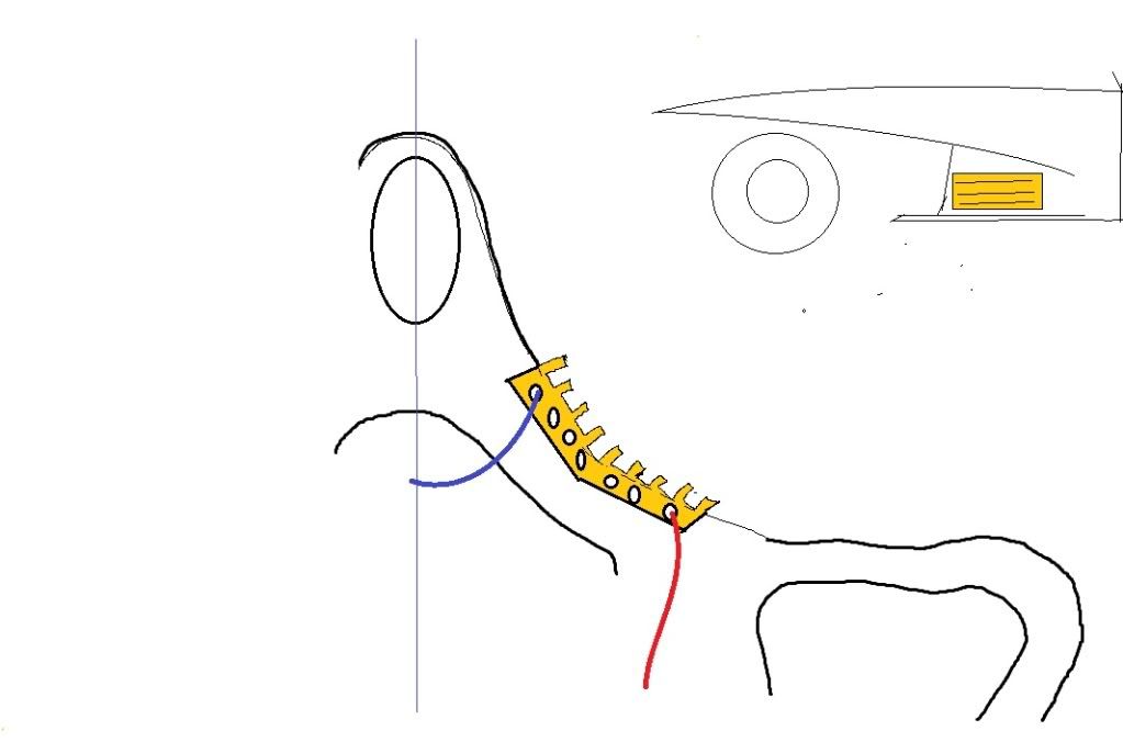
new exhaust and kers cooling solution coming on the weekend.

The KERS cooling is very brave. The brave end of the brave. 8)

Notice no KERS holes on the car?

Image

When it's up i want to hear the thoughts on it's legality.
For Sure!!

marcush.
marcush.
159
Joined: 09 Mar 2004, 16:55

Re: Ringo F1 design

Post

I´m looking forward to see your solution with Kers

Ringo ,I do not understand the leading edge of the sidepods It looks like the openeing is shaped knife edge ,not rounded at all.Is thois deliberate or just not ready yet? My personal feeling is the sidepods fattest crosssection should be more forward to allow for a more rounded inlet to the radiators.

as for the copper vs Aluminium ..a big issue with copper was the industrial mating of the copper tubes to frame /watertanks this was a lead7soldering process and it reduced the efficiency of the heattransfer significantly as a considerable length of copper tube is covered by tin/lead .
Today you can weld copper somebody will return to copper now..
http://www.copper.org/applications/auto ... tions.html

Robbobnob
Robbobnob
33
Joined: 21 May 2010, 04:03
Location: Auckland, New Zealand

Re: Ringo F1 design

Post

i agree with marcush on the sidepod openings, want to be rounded, like the inlet trumpets.

How are you determining KERS Cooling requirements?
"I continuously go further and further learning about my own limitations, my body limitations, psychological limitations. It's a way of life for me." - Ayrton Senna

User avatar
ringo
230
Joined: 29 Mar 2009, 10:57

Re: Ringo F1 design

Post

The side pod openings are not started as yet. The concept of the opening i have is to get a way with making some downforce of the shape of the inlet, as i have done a few tests with it, and it had less lift than the typical flat faced opening.

The KERS cooling, i don't know as yet.
The motor waste heat, the batteries i am not certain of. I'll have to try and infer from the efficiency of these things how much heat they putt off.

I suppose the KERS cooler has water being pumped through it.

What i will say is that the solution will have much less drag and lift and it also has another benefit.

Enough of the over-hyping, i'll try and get on with the work.
For Sure!!

User avatar
godlameroso
309
Joined: 16 Jan 2010, 21:27
Location: Miami FL

Re: Ringo F1 design

Post

ringo wrote:It's a quality of the wing.
The flow stays more attached at the end plate on a wing of such high camber.

Even with uniform flow at the front, it will still result with stronger up wash at the ends.

The Renault shaped wing and the Williams shaped wing in Canada demonstrates attempts to compensate for this phenomena as well. So do wings of the past years with slots in the middle.
Did you take into consideration the curvature of the endplates, and how they affect the cut out?
Saishū kōnā

User avatar
ringo
230
Joined: 29 Mar 2009, 10:57

Re: Ringo F1 design

Post

Yes. Though it doesn't change the behavior much.
Or maybe i don't have the capability to see the difference.

Flow near the end plate is ussualy the strongest; more upwash.

Sorry for the delays, just trying to find time to finish before the season is up.

Image

Image

Image

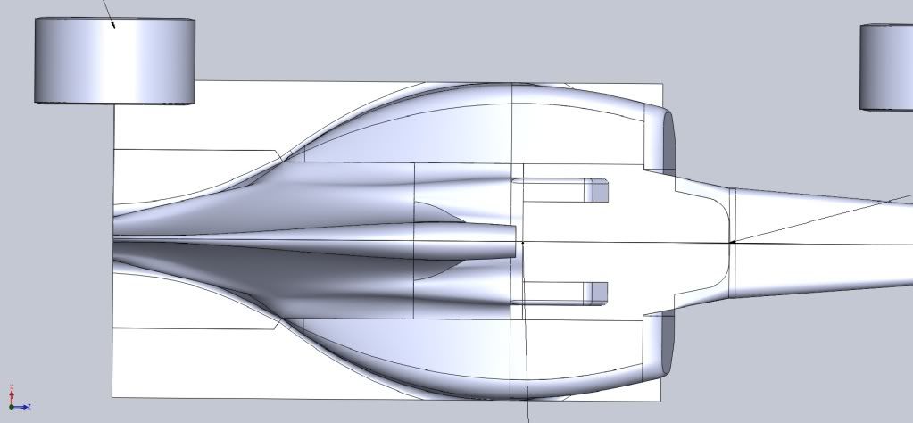
refined design.

KERS solution, bahh.. i'll just draw it in MS paint as the car is far behind schedule. :lol:
For Sure!!

User avatar
ringo
230
Joined: 29 Mar 2009, 10:57

Re: Ringo F1 design

Post

ringo wrote:Image

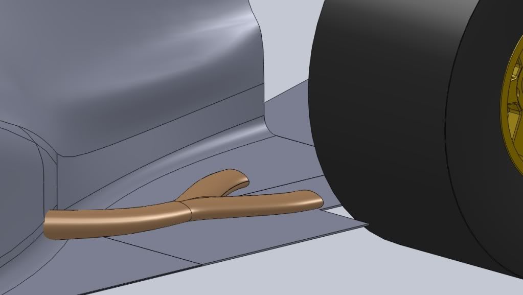
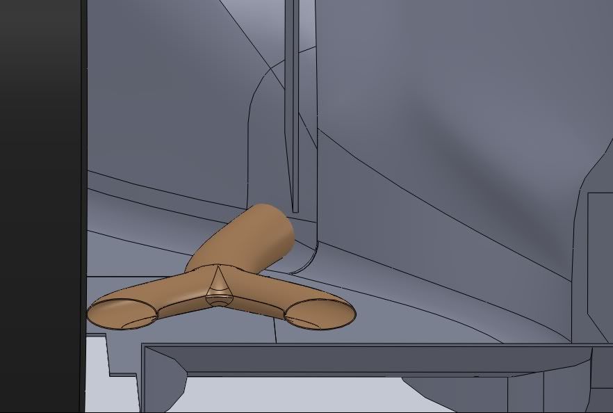
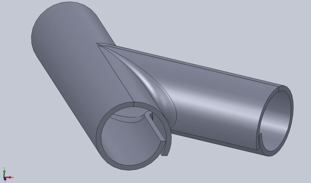
just made the concept to get a little practice before i form the final pipe on the car.

You can see from here that there is really one aperture.

edit: it's coiled the wrong way, but you guys get the idea.
reminder of the concept for new readers; incase someone asks why the pipe is legal.

If you look on the car, you will find that half is blowing to the side and the other half is impinging the top of the diffuser. So it's like half the mercedes concept and half redbull. I called it the real octopus exhuast; mclaren's was still born :lol: hope this isn't :D . Whether it's better than the redbull i don't know as yet.
For Sure!!

User avatar
ringo
230
Joined: 29 Mar 2009, 10:57

Re: Ringo F1 design

Post

Image

It seems that the Idea is to difficult to fit into the regulated areas lchecked the volumes and an air cooled fined heat sink will be crammed into to tight a volume to be effective. however ithinkafinned heat sink can go at the flanks of the bow of the car. Cooling fluid will flow through this heat sink block of metal. The sink can act as ballast as well. This is a throw back to the gordon Murray concept from the 80's?
For Sure!!