It just suddenly dawned on you that the plank will experience tension.

Your experiment is not very accurate. It's demonstrative but not accurate.
The plank is attached to a carbon fiber floor remember.
The combination of floor and plank does deflect see saw or not, and it is not as easy as you think. But what i am sying is that it is behaving like a cantilever. Which is normal behavior.
That same tension in the plank and carbon is why a see saw doesn't really make sense.
You forget to mention that the plank has to move with the floor as it is fixed to it; we've seen the fasteners.
So the limiting factor is the strain in the cabon floor. CFRP has small strains and the plank's stretch will be limited to that of the CFRP floor.
It's deflecting at the end, but it isn't separating in the middle like the seesaw theory suggests.
The irony with the see saw idea, is that if the plank doesn't separate at the 1000mm from the rest of the plank, which is correct, it would behave like a cantilever anyway.
check out these images and let's reason here:
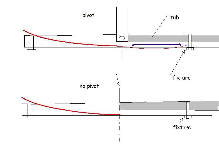
Above we have a pivoted floor and a non pivoted floor being deflected.
Note that both have fixtures, the rear most fixture being behind the wear marks where it is claimed the floor is bending about.
Logic dictates that the floor will not pivot because of the rear fixture to the CFRP floor and tub. The plank is not free to move as it is fixed.
All will happen is the floor will cantilever about the pivot and a little sagging will take place behind the pivot. The sagging and deflection is shown with the red line. The sagging is probably on a minuscule order.
Compared to the non pivoted, the isn't any difference. The floor simply cantilevers where it meets the tub.
Now for the see saw to work, this needs to happen:
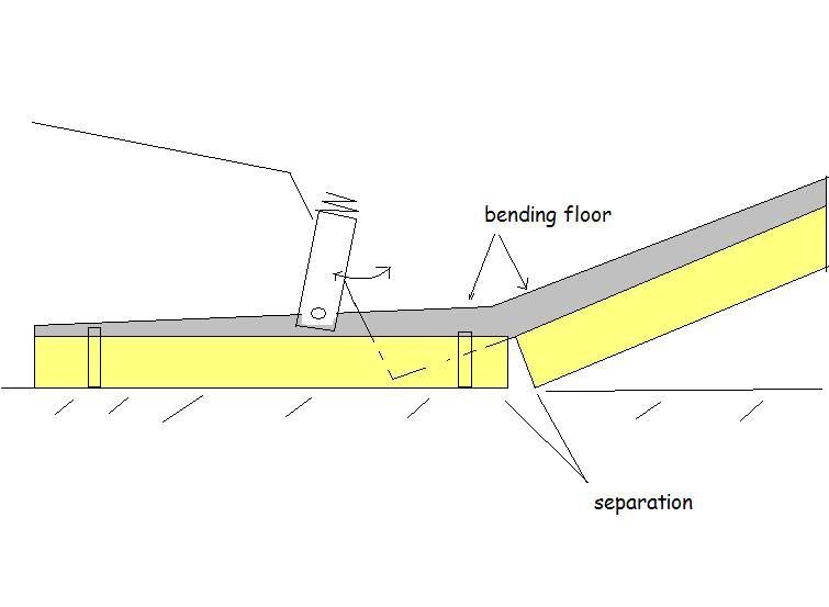
the fasteners need to be on the part of the floor that is deflecting. Also the pivot has to be able to rotate to avoid the system being a simple cantilever as explained above. The pivot must also be sprung.
Also the separtion has to take place between the first and second piece of plank and the CFRP has to be considerably weak to bend in this joint.
Finaly the tub itselft needs a hollowed out section in the plank to shift into, keeping in mind the tub is flat on the bottom and it is still following the line of the the rest of the non pivoted floor. You can see this hollowed out part where the tub must go.
All of the above is illegal anyway.
Another method is this:
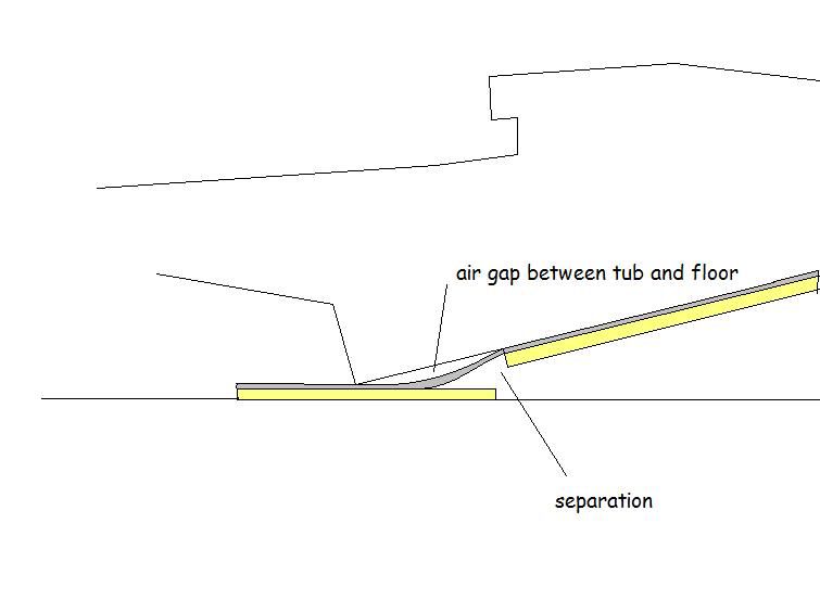
This is self explanatory, and completely illegal and almost not plausible with a solid 1 piece CFRP floor. Note that the plank and floor has to be pulled away from the tub to move into place on the ground.
So in summary, simply cantelvering the floor is the logical means to this, which all teams are doing.
Using shape memory alloy, heat warp mechanics for composites, or whatever other technology is also a possibility.