In the main volume of the diffuser, after the throat, is velocity decreasing and pressure increasing because of the increase in volume?
IF correct, is this SPECIFIC region producing a loss of downforce?
Brian
That would depend on the pressure above the diffuser.hardingfv32 wrote:In the main volume of the diffuser, after the throat, is velocity decreasing and pressure increasing because of the increase in volume?
IF correct, is this SPECIFIC region producing a loss of downforce?
Brian
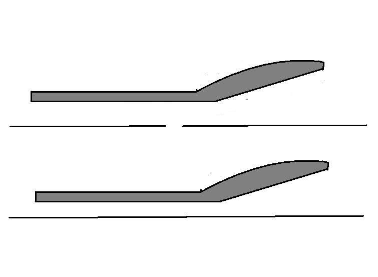
No, not the angle. The shape at the top surface has to be the same to have a fair comparison.DRCorsa wrote:@ringo
I didn't really understand the different top surface subject.
Maybe you mean the different angle of the diffusers between those 2 images? If yes, this has nothing to do with the analysis, the voncave one is just rotated on the post processor. The flow direction is parallel to the throat on both examples.
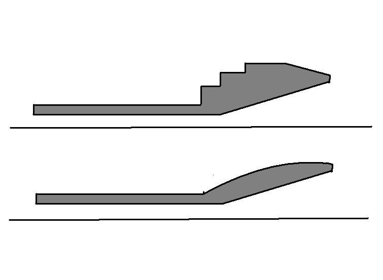
15 degrees is indeed a pretty radical angle. Try 10 to 12 degrees and put a gurney on the end of it if you can. The diffusers you see in F1 are using the beam and rear wing to reduce flow separation, though like I said before, all of this stuff is interrelated carefully to make it actually work.hardingfv32 wrote:Actually the best I could find was flow over a stepped surface. This is the closest I could get to the shape we are seeing at the throat of the concave diffuser. I do appreciate that we don't know how much of a radius is being used at the throat.
I found a number of studies of flat roofs that show tremendous separation at with say a 15 deg slope. How are we going to remain attach with this concave shape if that is the case with a 15 deg sloped flat roof?
I think there is a compromise being made between separation and something else with the concave shape that is a net gain of something that we do not appreciate at this point.
I need new descriptors for more searches. Concave is getting me nothing.
Brian
I did it and the picture is more or less the same.ringo wrote:I see,
but what's on the outside, still air?
Your results are probably correct in terms of which one has less drag etc. but you just don't know if it is in the correct proportion.
Also you may not be sure if the still air on the outside is affecting your results; is being pulled by the diffuser flow etc.
Anyway, for argument's sake could you change your model and run the test again?
This time with a floor 4 times longer than the diffuser and a common top surface. Do an external flow simulation.
These comparisons say it all really. One is stalled with the separation bubble. The other has smooth flow.DRCorsa wrote:I did it and the picture is more or less the same.ringo wrote:I see,
but what's on the outside, still air?
Your results are probably correct in terms of which one has less drag etc. but you just don't know if it is in the correct proportion.
Also you may not be sure if the still air on the outside is affecting your results; is being pulled by the diffuser flow etc.
Anyway, for argument's sake could you change your model and run the test again?
This time with a floor 4 times longer than the diffuser and a common top surface. Do an external flow simulation.
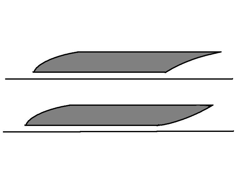
For the concave, downforce and drag levels are lower, there is the suction peak at the kink line and there is notably less downforce and stall after the kink line.
CONCAVE
Downforce: 1473N
Drag: 317N
CONVEX
Downforce: 2077N
Drag: 396N