Mclaren Mp4-26 "Fan tail" Exhaust

Here are our CFD links and discussions about aerodynamics, suspension, driver safety and tyres. Please stick to F1 on this forum.
scarbs
scarbs
393
Joined: 08 Oct 2003, 09:47
Location: Hertfordshire, UK

Re: Mclaren Mp4-26 "Fan tail" Exhaust

Post

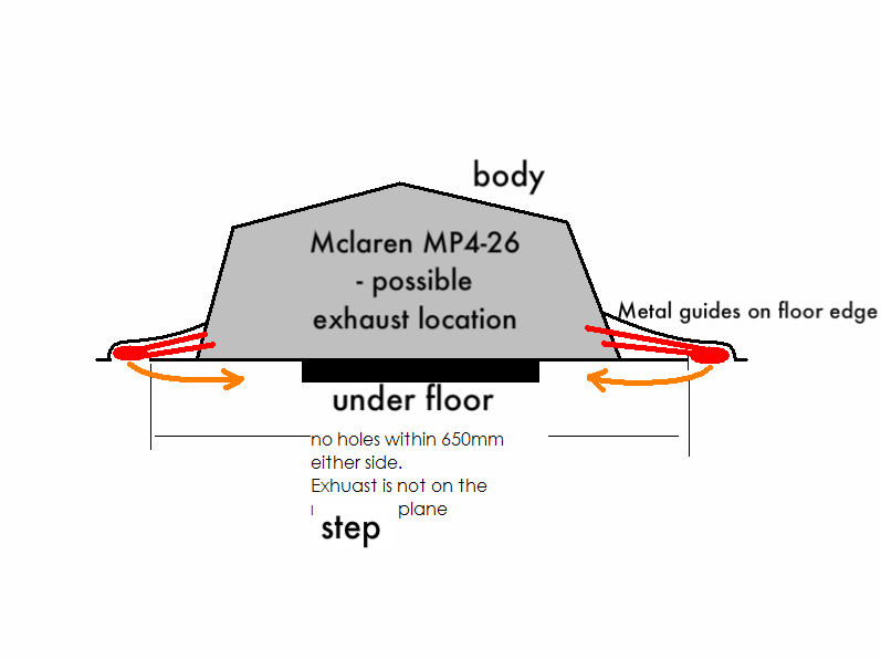
I spoke to Paddy at the launch, he explained it all to me and even drew a picture of it on my pad! The exhausts spread sideways and flatten to create a longitudenal slot exit. This slot faced downwards 50mm from the edge of the floor. The set up needed a small cut to make the slot join to the periphery of the floor, to make it legal. The exhaust effectively blew downwards which although creates lift by itself, also created a skirt to seal the floor.

I hope to get a pic of it from McLaren (Piola has one). I'll do a blog post on the subject, once these pesky 2012 launches are all out of the way.

This is it fitted: http://scarbsf1.files.wordpress.com/201 ... clubs1.jpg

My previous drawing of it: http://scarbsf1.files.wordpress.com/201 ... n_slit.jpg

Pup
Pup
50
Joined: 08 May 2008, 17:45

Re: Mclaren Mp4-26 "Fan tail" Exhaust

Post

Can't wait to read it.

I'm guessing that your photo shows the cut (slit) at the top? Is what looks like a cutaway at the rear just an illusion? And was this the original concept, or the backup? Too many questions...

And re stig84's comment, I think we'd love to put these two mysteries to rest as well, if you know the answers...

Image
Image

scarbs
scarbs
393
Joined: 08 Oct 2003, 09:47
Location: Hertfordshire, UK

Re: Mclaren Mp4-26 "Fan tail" Exhaust

Post

The double thickness floor was the fan tail solution, everything else were just back up solutions. The car barely ran with the fantail fitted, the slot above I assume was just to help cool the set up.

IIRC the upper picture shows the tyre temp sensor in the splitter and the lower picture showed the bundles of tubes used for the aero rake fitted at that test.

User avatar
horse
6
Joined: 23 Oct 2009, 17:53
Location: Bilbao, ES

Re: Mclaren Mp4-26 "Fan tail" Exhaust

Post

I wonder if there is any feeling for whether this solution was better than the RB solution, had the McLaren solution worked?

My personal feeling is that it wouldn't be particularly, given that the exhaust was angled down (as your drawing suggests) rather than parallel to the direction of motion.

I don't know, perhaps applying the exhaust to the diffuser further forward along the floor carries greater benefits, but it all seems rather "inelegant".

Is there any evidence of sports car exhaust being utilised in this way yet, by the way, anyone?

EDIT: Generalised it as it didn't light the imagination of the man on the inside.
Last edited by horse on 10 Feb 2012, 11:01, edited 3 times in total.
"Words are for meaning: when you've got the meaning, you can forget the words." - Chuang Tzu

User avatar
PlatinumZealot
558
Joined: 12 Jun 2008, 03:45

Re: Mclaren Mp4-26 "Fan tail" Exhaust

Post

scarbs wrote:The double thickness floor was the fan tail solution, everything else were just back up solutions. The car barely ran with the fantail fitted, the slot above I assume was just to help cool the set up.

IIRC the upper picture shows the tyre temp sensor in the splitter and the lower picture showed the bundles of tubes used for the aero rake fitted at that test.
So Scarbs old boy. :wink: Remember this sketch I made? I did it in February. It was literally one month ahead of it's time. The rest of the F1 media, including yourself didn't figure it out until one month after. :wink:

Image

I was saying octopus is no octopus from a long time ago.
πŸ–οΈβœŒοΈβ˜οΈπŸ‘€πŸ‘ŒβœοΈπŸŽπŸ†πŸ™

Racing Green in 2028

scarbs
scarbs
393
Joined: 08 Oct 2003, 09:47
Location: Hertfordshire, UK

Re: Mclaren Mp4-26 "Fan tail" Exhaust

Post

Indeed your idea was pretty much spot on....

User avatar
PlatinumZealot
558
Joined: 12 Jun 2008, 03:45

Re: Mclaren Mp4-26 "Fan tail" Exhaust

Post

scarbs wrote:I spoke to Paddy at the launch, he explained it all to me and even drew a picture of it on my pad! The exhausts spread sideways and flatten to create a longitudenal slot exit. This slot faced downwards 50mm from the edge of the floor. The set up needed a small cut to make the slot join to the periphery of the floor, to make it legal. The exhaust effectively blew downwards which although creates lift by itself, also created a skirt to seal the floor.

I hope to get a pic of it from McLaren (Piola has one). I'll do a blog post on the subject, once these pesky 2012 launches are all out of the way.

This is it fitted: http://scarbsf1.files.wordpress.com/201 ... clubs1.jpg

My previous drawing of it: http://scarbsf1.files.wordpress.com/201 ... n_slit.jpg
You should ask them some "burning" questions next time out. You see, we have this Inertial mercury thing we want to clear up with Mercedes. Not the regular interters who's fluid inertia stretches only to internal damping, but the Inertial mercury damping as suggested by abudaliaf1.
πŸ–οΈβœŒοΈβ˜οΈπŸ‘€πŸ‘ŒβœοΈπŸŽπŸ†πŸ™

Racing Green in 2028

scarbs
scarbs
393
Joined: 08 Oct 2003, 09:47
Location: Hertfordshire, UK

Re: Mclaren Mp4-26 "Fan tail" Exhaust

Post

n smikle wrote:You should ask them some "burning" questions next time out. You see, we have this Inertial mercury thing we want to clear up with Mercedes. Not the regular interters who's fluid inertia stretches only to internal damping, but the Inertial mercury damping as suggested by abudaliaf1.
You think I havent already? I understand Mercury is banned. The interlinked suspension proposed by AdudaliaF1 based along the 1960's Austin Hydrolastic system, has been used in F1 since 2009! and is in use by over four teams currently. I have knowledge ot two teams that were workng on it in 2011.

bhall
bhall
244
Joined: 28 Feb 2006, 21:26

Re: Mclaren Mp4-26 "Fan tail" Exhaust

Post

scarbs wrote:I understand Mercury is banned. The interlinked suspension proposed by AdudaliaF1 based along the 1960's Austin Hydrolastic system, has been used in F1 since 2009! and is in use by over four teams currently. I have knowledge ot two teams that were workng on it in 2011.
Early contender for Post of the Year.

I can't tell you how valuable that information is currently, and it's quite literally impossible to overstate that value had the information materialized about 40-50 pages ago in the Mercedes thread.

User avatar
horse
6
Joined: 23 Oct 2009, 17:53
Location: Bilbao, ES

Re: Mclaren Mp4-26 "Fan tail" Exhaust

Post

So, returning to the technology, I'm guessing they had to fan it out in order to reduce the amount of lift that would have been caused if you just had one narrow channel like the RB system that was pointing down.

The question I have is why didn't RB finish their exhausts under the floor also? I mean they could have chosen to use a similar argument to not breaking the rules as this system uses, so why not dip below the floor right at the very end just before the cut outs? Instead they still chose to exit the exhausts above the floor.
"Words are for meaning: when you've got the meaning, you can forget the words." - Chuang Tzu

Richard
Richard
Moderator
Joined: 15 Apr 2009, 14:41
Location: UK

Re: Mclaren Mp4-26 "Fan tail" Exhaust

Post

What surprises me about Lowe's comments is that the back up approach with two pipes stuck out the back had more problems than the fan.

@n smikle - aswsome job digging out those pics!

User avatar
PlatinumZealot
558
Joined: 12 Jun 2008, 03:45

Re: Mclaren Mp4-26 "Fan tail" Exhaust

Post

scarbs wrote:
n smikle wrote:You should ask them some "burning" questions next time out. You see, we have this Inertial mercury thing we want to clear up with Mercedes. Not the regular interters who's fluid inertia stretches only to internal damping, but the Inertial mercury damping as suggested by abudaliaf1.
You think I havent already? I understand Mercury is banned. The interlinked suspension proposed by AdudaliaF1 based along the 1960's Austin Hydrolastic system, has been used in F1 since 2009! and is in use by over four teams currently. I have knowledge ot two teams that were workng on it in 2011.
I have read your aticles. No problem with those systems you have shown. But if you are so inclined, you will realise there is one key difference with Abudalia's system vs the other systems. That difference is not mentioned in your blog.

It is not mentioned here either... http://www.bluestreaksix.com/Austin1800/Page16.html


Usually when you design machines, a lot of effects are assumed insignificant.
An extreme example: the gravity of each individual part of a car (each part has it's own gravitational field yes?) - but there might be cases in other machines where the gravity of parts have to be considered. As I said an Extreme example.

Now going by the above reasoning. In the system proposed by abulafia (or his friend?) the inertial effect comes to the fore front. Normally only utilised in increasing damping ratios, the Inertial effect is now instead a prime mover. Actually providing the force behind moving the suspension corners.

I and a few other members did some calculations, and we saw significant forces required. I myself, have noted that the system is also sensitive to differences in gravitation potential - front from back, (which is normal) but because of the density of the Hg it produces a significant levelling effect whenever it "senses" differences in gravitational potential. I suspect that this effect can be another input into the suspension system as it is out of phase with the wheel loads. It actually produces a "leading phase difference" (for the electrical people out there) I would appreciate it if you to ask the engineers about this effect.

You can call it a "gravity levelling system." But yeah back onto the topic of the fan exhaust.
πŸ–οΈβœŒοΈβ˜οΈπŸ‘€πŸ‘ŒβœοΈπŸŽπŸ†πŸ™

Racing Green in 2028