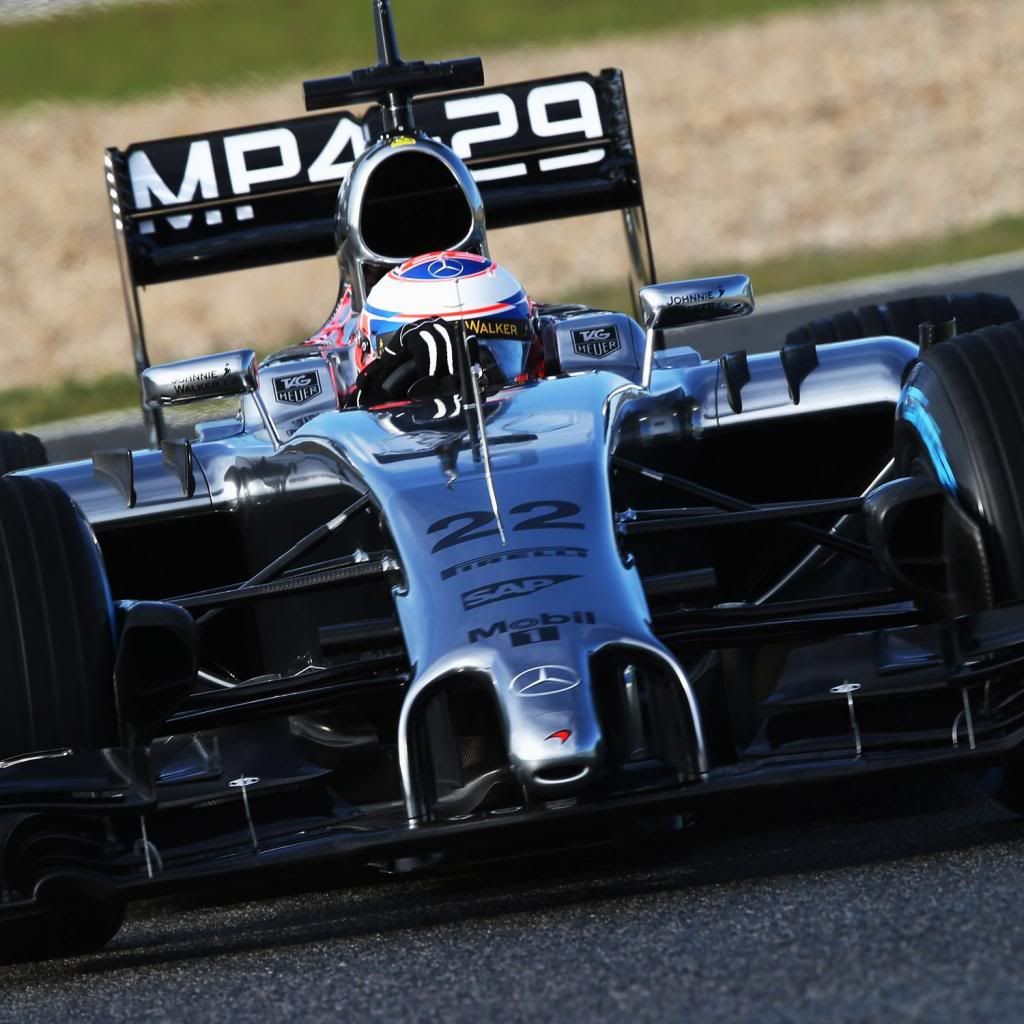
Gridlock wrote:I find it interesting everything about this system seems to be in a pair - two inlets, two tubes, etc. Does this suggest that each side of the car can be stalled individually, depending on the difference in pressure across the inlets? Creating in effect an aero-assisted turning aid in principle not different to McLaren's split brake pedal.
That is a really good point. Before we saw so much of this system, we could only speculate, now we know it inded comes in twos. These two pipes come very very close together at the crash structure and around the bulkhead. It follows that they could have been fused to one slightly larger pipe between the crash structure and the bulkhead saving some weight (relatively high in the car) at the price of having an assymetric pipe, which I would think is rather small.
Whiteblue cited simplicity and redundancy in the design, but I am still to see a F1 team trade that for a higher COG, so I'll assume that is not the case.
For the following discussion, I'll assume that the holes in the rear wing are indeed in a high pressure area and meant to collect flow, and that the tubes carry air from the rear wing to the front wing. I know there is no consensus yet of that being indeed the case, but for the sake of discussion, let's assume so.
This is a very simple scheme of the situation in that case, representing only the front wing and the rear wing.
In a straight:
_________                  _______
|        |                |       |
|        |________________|       |    Front wing
|_________________________________|
  Stall                     Stall
                                         ||
                                         || Wind
                                         \/
 _________________________________
|                                 |
|                                 |    Rear wing
|_________________________________|
  High                       High
 Press.                     Press.
In a left handed corner, and I have added the duct connections to the scheme:
_________                 _______
 \       \                \      \
  \       \________________\      \     Front wing
   \_______________________________\
    Stall                  Stall
      ||                      ||
      ||                      ||         ||
      ||                      ||         || Wind
      ||                      ||         \/
 _________________________________
 \                                \
  \                                \    Rear wing
   \________________________________\
     High                    High
    Press.                  Press.
Now the car is turning and it will have a (small) yaw angle. Hence the air is hitting the rear wing asymmetrically, ramming against the end plate in the inside of the corner, increasing the local high pressure, while the hole in the outer end plate is shadowed by the end plate itself, reducing the local high pressure. It follows that the flow would be higher in the inside pipe than in the outside pipe, and hence the stall would be more pronounced in the inside side of the front wing.
This difference in local pressure and flow at the DRS hole intakes (basically having two flows of different strengh) hints at a possible reason to keep two pipes: a joint at the crash structure would offer a short circuit route for part of the air to go from the inside end plate of the rear wing directly to the outside end plate, never reaching the front wing.
It also opens an intriguing possibility: that the pipes cross over, either at the crash structure or, I'd think more likely, af the front wing right after the bulkhead but before the pylons. The new flow and stall diagram would look like this (note the crossing pipes):
_________                 _______
 \       \                \      \
  \       \________________\      \     Front wing
   \_______________________________\
    Stall      \\   //       Stall
               \\ //
                \X/                     ||
                /X\                     || Wind
               // \\                    \/
 _____________//___\\_____________
 \                                \
  \                                \    Rear wing
   \________________________________\
     High                    High
    Press.                  Press.
What are the implications of this? I'd leave a more thorough discussion to the vehicle dynamics gurus here, but I'd think that in the latest scenario, with crossed pipes, the different stall of both sides of the front wing would result in the inside part of the front wing plate being more loaded than the outside, creating a torque that would be transmitted through the nosecone and try to level the car against its natural tendency to roll in the corners. Whether there is much of an advantage in this, I am not so sure.
Disclaimer: Just wild speculation here, no sources involved or to be blamed.


