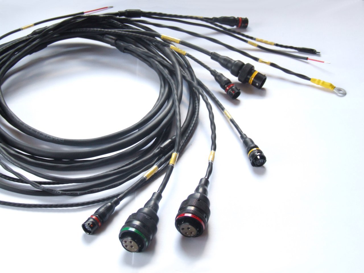
F1 Wire Harness design and build

All that has to do with the power train, gearbox, clutch, fuels and lubricants, etc. Generally the mechanical side of Formula One.
mzivtins
mzivtins
9
Joined: 29 Feb 2012, 12:41

F1 Wire Harness design and build

Post

Sorry this post is going to seem like i haven't bothered with the search function :oops:

Couldn't really find what i wanted, so...

I have assumptions based on things i know about wire harness design in other racing series... can i assume that we would see probably NO soldering of conductors within and F1 harness?
That the entire affair is at least mil-spec?
From the pictures in the F1 car threads, they look like they are using Deutsch connectors/terminators?
Using spec 55a conductor?

Who can give me a definitive answer :twisted: or point me in the direction for one?

The reason... i am sick of people still blithering on about soldering in motor vehicles being better than crimping... and then even saying the same for motor racing. I just feel its so old fashioned and not fit for purpose :roll:

Who knows, maybe they are correct, and mil-spec crimping is a pile of shite and caused voltage drop over the crimps enough to cause sensative sensors to malfucntion :lol:

langwadt
langwadt
35
Joined: 25 Mar 2012, 14:54

Re: F1 Wire Harness design and build

Post

....

I haven't seen the wiring harness in an F1 car, but I cannot imagine they use anything but crimp, it is the best and most realiable. I doubt you can even get the connectors they use with anything other than crimp

Solder is bad because it flow in between cores on a wire makes it brittle so with vibration it is likely to break.
Even worse is tinning and then crimping or screwing, because solder cold flow so it will go loose

but of course, if you don't have the right tools and just use what ever pair of pliers you can find to do the crimps solder might be better ...
Last edited by mx_tifoso on 11 Jul 2012, 22:18, edited 1 time in total.
Reason: no need to quote op

riff_raff
riff_raff
132
Joined: 24 Dec 2004, 10:18

Re: F1 Wire Harness design and build

Post

mzivtins-

In aerospace, crimping is used almost exclusively. The reason being that it is much easier to control the quality of a crimped wire termination than one that is soldered. Due to the availability of high performance aerospace connectors with crimped pins, I'd imagine that's what F1 would use.
"Q: How do you make a small fortune in racing?
A: Start with a large one!"

Tommy Cookers
Tommy Cookers
646
Joined: 17 Feb 2012, 16:55

Re: F1 Wire Harness design and build

Post

crimping works on the basis that a whole-life connector to wire resistance in the milliOhm range is tolerable ?

(as it would be in any normal application, including F1 sensors, but for some special purrposes outside F1 crimping is unacceptable on the above grounds)

Aerospace is a benign environment regarding humidity and contact corrosion
Computors live in humidity conditioned situations


Q Are we talking about copper wire/gold plated connector or both wire and connector gold plated ??


Also isn't the wire insulation material a problem ?

'Aerospace' mandates unusual heat tolerance, but such insulation materials (polyimide or PTFE) are relatively brittle and unsuited to the disruption of removal and refitting of closely packed wiring ?

James Price
James Price
0
Joined: 22 Jul 2012, 00:56

Re: F1 Wire Harness design and build

Post

you might find this paper useful

Racing design lags behind its peers in the commodity automobile industry in some key respects, particularly in the realm of electrical design. This paper explains how today’s automated ECAD tools, widely used among consumer OEMs, can help race teams bring reliable, compact, cost-effective electrical system designs to their platforms in minimal time.

http://www.mentor.com/products/electric ... 9c83857081

User avatar
Pierce89
60
Joined: 21 Oct 2009, 18:38

Re: F1 Wire Harness design and build

Post

James Price wrote:you might find this paper useful

Racing design lags behind its peers in the commodity automobile industry in some key respects, particularly in the realm of electrical design. This paper explains how today’s automated ECAD tools, widely used among consumer OEMs, can help race teams bring reliable, compact, cost-effective electrical system designs to their platforms in minimal time.

http://www.mentor.com/products/electric ... 9c83857081
I really wouldn't consider an F1 spec CAN-BUS system as lagging behind the electrical architecture in my mid 2000's Toyota.
“To be able to actually make something is awfully nice”
Bruce McLaren on building his first McLaren racecars, 1970

“I've got to be careful what I say, but possibly to probably Juan would have had a bigger go”
Sir Frank Williams after the 2003 Canadian GP, where Ralf hesitated to pass brother M. Schumacher

langwadt
langwadt
35
Joined: 25 Mar 2012, 14:54

Re: F1 Wire Harness design and build

Post

Pierce89 wrote:
James Price wrote:you might find this paper useful

Racing design lags behind its peers in the commodity automobile industry in some key respects, particularly in the realm of electrical design. This paper explains how today’s automated ECAD tools, widely used among consumer OEMs, can help race teams bring reliable, compact, cost-effective electrical system designs to their platforms in minimal time.

http://www.mentor.com/products/electric ... 9c83857081
I really wouldn't consider an F1 spec CAN-BUS system as lagging behind the electrical architecture in my mid 2000's Toyota.
not a big surprise that mentor, a company that makes automated ECAD tools, makes a white paper about how a tool they want to sell you can fix all the worlds problems ;)

marcush.
marcush.
159
Joined: 09 Mar 2004, 16:55

Re: F1 Wire Harness design and build

Post

I´d think all the wire to pin connections are crimp -which is basically resulting in a weldlike joint if executed properly.this is the one an donly method for anything related to lamda sensors in the automotive industry..maybe some plasma or laser welding but soldering stops with smd positioning on circuit boards and even those are quite tricky to stay on top in development-temperature shock the biggest issue ,especially with todays leadfree soldering...

hardingfv32
hardingfv32
35
Joined: 03 Apr 2011, 19:42

Re: F1 Wire Harness design and build

Post

marcush. wrote:I´d think all the wire to pin connections are crimp -which is basically resulting in a weldlike joint if executed properly.
'weldlike joint if executed properly'

This is exactly what a properly crimped connection using a ratchet type crimper looks like... One solid piece of metal. It requires a properly calibrate and maintained crimper. Test samples have to be make, sectioned, and inspected to meet your requirements.

Brian

mzivtins
mzivtins
9
Joined: 29 Feb 2012, 12:41

Re: F1 Wire Harness design and build

Post

Excellent, thanks for all the posts guys... I just couldn't believe that anyone would go near a aerospace grade harness with a soldering iron.

Looking at some of the pictures in the car specific threads, i can see the use of raychem heat sink boots and what look like deutsch automotive moulded parts... the mclaren f1 and the mp4-12c use mil-spec autosport connectors, all 100% crimped... the look of the deutsch stuff is unmistakable:

Image

Glued shrunk boots on the mclaren f1 crimped wire harness:
Image

So one would guess, f1 must exclusively use one type of connector and crimp... i'd love to know which, as i'm looking at using deutsch automotive DT & DTM connectors in my harness build, but maybe, being such an advertising whore, would look towards the equipment suppliers that f1 teams chose... but for the life of me... i really can't see them using anything other than deutsch autosport?

mzivtins
mzivtins
9
Joined: 29 Feb 2012, 12:41

Re: F1 Wire Harness design and build

Post

had a look around, and you can really see that all the harness terminations are the Deutsch Autosport AS Series connector, i would then guess they would be using the Raychem spec-55 wire, which is not PFTE but something called TFTE insulated i believe.

This spec-55/55a wire when used with the Deutsch crimps actually cold welds the tiny strands of wire into one mass including the crimp (as stated earlier in this thread, its like a weld!)

The AS series connectors are HUGELY expensive, even the cheaper style of connectors can be around £50 for one terminal!

Check out the lotus with them:
Image

and the bare terminal:
Image

Given all that we can see, can we safely say that within the harness an f1 car would NEVER use solder? i wish an f1 mech could let us know?

It makes sense as crimp work out in the field is the same quality as in the factory, wheras soldering brings challenges that may give very inconsistent results...

Tommy Cookers
Tommy Cookers
646
Joined: 17 Feb 2012, 16:55

Re: F1 Wire Harness design and build

Post

I've just checked your sources (and Mr Google, the same areas of controversy are still active, some even swear by crimping combined with light soldering)

officially 'cold welding' is not claimed I think ?? (fridge heat exchangers have been made this way for 60+ years though)
nothing (eg in F1 or Aerospace) should need external connection down in the microOhm region (formerly my interest)


the whole electric KERS/'TERS thing is a greater issue ?

Webby308
Webby308
6
Joined: 24 Jul 2012, 14:21

Re: F1 Wire Harness design and build

Post

Thanks for all the Deutsch mentions!

If I can add to this one - I have worked for Deutsch Autosport for the past 11 years or so. For those who don't know what we do, we supply all the F1 teams, all the WRC teams, all the NASCAR Sprint Cup teams, all the Indycar teams, all the MotoGP teams, well you get the idea anyway.

Most people in professional level motorsport (those that use sensing and logging) tend to use Deutsch Autosport (thanks!) and Raychem system 25 for the wire, sleeving and boots.

All the AS connectors use crimp technology based on the mil spec 38999 series 1.5 (which is where the AS range originated from back in 1993). Before that date there was no such thing as an "Autosport" specific connector and teams used a selection of mil-spec stuff and anything else that they could obtain. In 1993, Williams and Benetton came to Deutsch to ask for a range of mil-spec parts they could get a reliable supply of. Thankfully that's just what we did - plus our distibutor at the time put a million pounds worth on the shelf as availability is key as raceteams don't really go in for forecasting demand...

The crimp technology is used for reliability generally. If your crimp tool is setup right (and calibrated) then you can perform thousands of reliable crimps that meet the minimum spec for strength and conductivity. Soldering is not always so precise... The connectors we have developed since, ASL, ASU and ASX do not actually apply to the mil standard (they are much smaller and lighter than anything the military use) however we do subject them to the same test and qualification procedure. Actually an F1 gearbox is a tougher environment than the gunfire test 38999 requires...

Raychem's system 25 generally uses 55A wire for most forms of racing, but F1 and MotoGP will go for the lighter and stronger 55M version. The Raychem DR 25 tubing will cover the wire bundle, which should be contra-twisted for the best flexibility and strength. A heatshink boot finishes off the loom. On a pure mil-spec connector there is a screw thread on the back of the connector for a back fitting. Only 1 team in motorsport I can think for prefers this to the boot solution.

Hopefully that lot is useful, but I'm happy to answer any specific connector/harness type questions.

Paul Webb
Sales and Marketing Manager
Deutsch Autosport.

Scootin159
Scootin159
9
Joined: 06 Aug 2009, 21:09

Re: F1 Wire Harness design and build

Post

Some simple questions you can probably answer:

What are typical parts costs for one of the connectors used? Any idea what the Raychem 55M wiring costs? Obviously both are dependent on the number of connectors.

What do the crimp side of the connectors look like? Do you crimp a terminal plug on each conductor separately, and then slip them all into the connector?

What materials are the parts made out of? The connectors look like aluminum in the pictures, but something tells me they're made out of titanium instead...

gato azul
gato azul
70
Joined: 02 Feb 2012, 14:39

Re: F1 Wire Harness design and build

Post

Scootin159 wrote: What do the crimp side of the connectors look like? Do you crimp a terminal plug on each conductor separately, and then slip them all into the connector?
not him, but yes, each terminal is crimped individually and then "pined" into the connector housing, using another tool.

you may find this interesting, and it shows the crimping and pin in/out process in detail

http://www.ismotorsport.com/pdfs/Deutsc ... manual.pdf